This thread has been locked.

If you have a related question, please click the "Ask a related question" button in the top right corner. The newly created question will be automatically linked to this question.

INA823: INA823 nA current measurement

Part Number: INA823
Other Parts Discussed in Thread: INA283, TINA-TI

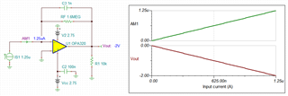
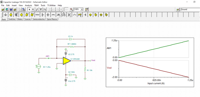
Hi, I need to use this circuit INA823 for nA current measurement, could I be recommended values for R1/R2/R3 for 0-1250nA measurement with 1nA-10nA accuracy if possible? 

I would like the 0-1250nA current to translate to output voltage 0-2V. Can the INA823DT do this?

  • Hi Amar,

    there's no simple answer. It depends on your application. Please tell more about your application? Where is the current coming from? What is the common mode voltage. Is is a low side measurement (recommended) with the common mode voltage near signal ground? Or is it high side measurement (not recommeded) with a high common mode voltage. What is your signal frequency range?

    In a low side measurement you should use a shunt of at least

    R = 20µV / 1.2nA ~ 17k

    where 20µV is the input offset voltage and 1.2nA is the input bias current of INA283. Otherwise the input offset voltage will add an additional error which is higher than the input bias current of INA283. To keep the error resulting from the input offset voltage smaller than the error resulting from the input bias current of INA283 you would even need to increase the shunt resistance above 17k.

    Can your circuit accept a shunt resistance of about 100k?

    Then, 1250nA times 100k gives a voltage drop of 125mV.

    Can your circuit accept such a voltage drop across the shunt?

    Another sort of current measurement uses a TIA where the measuring current runs into the -input of OPAmp which plays the role of a virtual ground. In this case a simple OPAmp could do and no additional voltage drop across a shunt would occur. But your application must allow the measuring current to flow into signal ground (virtual ground).

    So, the crucial point here is: What is your exact application?

    Kai

  • Hi Amar,

    Kai has provided you with very detailed reply. It will be good if you are able to share with us about the design application. 

    Best,

    Raymond

  • Hi Kai, 

    Thank you for these questions. Application is applying a voltage 0-60V across capacitor and measuring leakage current. How do I determine what common mode voltage is? Voltage will be applied to a capacitor between 0-60V. I think I will be using low-side measurement. Yes 100k shunt resistance seems fine

  • Hi Amar,

    You may use the TIA circuit to convert current to voltage. Please see attached schematic. Or you may use OPA2328, which it has better Vos figures or perform of measurement calibration prior to the leakage measurement. 

    Capacitor Leakage TIA 05162022.TSC

    Best,

    Raymond

  • Thanks! Will try this.

  • Hi Amar,

    this is isn't so simple. You might want to read this appnote:

    capacitance-leakage-measurement-to.pdf

    Kai

  • Sounds good. How was the graph produced in the simulation above? I am using TINA-TI to open your model.

  • Hi Amar,

    what capacitance values do you have? How do you initially charge up the capacitance? Would the OPAmp circuit have to withstand the inrush current (first moment charge current)?

    Kai

  • Hi Kai, the device I am testing behaves like a capacitator so I am not sure of its exact capacitance. I am also not sure of what the exact inrush current should be.

    Amar

  • Hi Amar,

    You may find a constant current source and momentarily inject current (dt) into an unknown capacitor, and measure dV/dt change and calculate capacitance value based on Cdv/dt = i. 

    The inrush current is the peak current when 60V is turned on momentarily, where a surge of current will go through the capacitor instantly. If you increase the applied voltage gradually, the inrush current should not be high and is able to control or regulate it. You may use soft start circuit to apply voltage across an unknown capacitor or using a voltage ramp circuit to charge up an capacitor gradually. 

    If you have additional questions, please let us know. 

    Best,

    Raymond

  • Hi Amar,

    can you show an equivalent circuit model of your "capacitor"? Or can you give any other details on your application?

    Kai