This thread has been locked.

If you have a related question, please click the "Ask a related question" button in the top right corner. The newly created question will be automatically linked to this question.

INA190: INA190

Part Number: INA190
Other Parts Discussed in Thread: INA237, INA236, INA238, INA228, INA229, INA121, INA191, INA2191

Hi there, we are planning to use the INA190 in our project to measure the system current in Active Mode and Sleep Mode.

Here are some details:

a. The INA190 will be used in Unidirectional High-Side Configuration

b. We want to measure a current of 100uA in Sleep Mode and around 300mA in Active Mode and the supply voltage is around 3.3VDC

c. INA190 has a very low input bias current, so that should not affect the our current measurement values since its way below the minimum threshold

d. The INA190 has an offset voltage of around 15uV so that means that the Min Vsense across the shunt has to be 1.5mV for the Offset Error to be 1%?

I have done various calculations and it seems difficult to use a single SHUNT and a single INA to accurately measure the current in the range of 100uA~300mA without compromising too much on Burden Voltage, Power Dissipation and Accuracy in %.

Are there any INAs or Solutions from TI that is better suited for the above use scenario? 

Thank You

  • Hi Adnan,

    yes, this IS difficult because you need a range of factor 300mA / 100µA = 3000.

    A shunt of 100mR would cause a voltage drop of 30mV at 300mA. This would be less than 1% of 3.3V. At 100µA the voltage drop would be 10µV then. You could adjust the offset voltage error of INA190 in the software, provided a µC is reading the INA190. You could even adjust the offset voltage drift in the software.

    Or you can do a low side measurement and take a chopper OPAmp with a lower maximum input offset voltage than 15µV:

    https://www.ti.com/amplifier-circuit/op-amps/precision/products.html#p2max=0.002;0.01&sort=p2max;asc

    Kai

  • Hey Adnan,

    I am looking into this and will respond shortly.

    Sincerely,

    Peter

  • Hey Adnan,

    Yes Kai is correct that the dynamic range you require is beyond the capability of the INA190. A basic calculation for the INA190 dynamic range is Vout_max/Vout_min = 4.95V/10mV = 495 < 3000.

    The options available are:

    1. Use a current/power monitor with relatively high input impedance (e.g., INA229, INA228, INA238, INA237, INA236). Vos_max = 1uV. To reach a 3000:1 dynamic range, the minimum shunt voltage (at 100uA) is Vsh_max/3000 = 163.84mV/3000 = 54.6uV. However, this yields a 1.83% error just from offset. Gain error can contribute max 0.05%. This may or may not exceed your max required system error. These device have input bias current in nA range.

    https://www.ti.com/amplifier-circuit/current-sense/power-current-monitors/products.html#sort=p766max;asc

    2. Use an instrumentation amplifier (e.g., INA121). The usual tradeoffs to using instrumentation amplifiers (which are usually very high input impedance) are that they require larger supply voltages and/or dual polarity supply voltages to operate on high voltage bus rails.

    https://www.ti.com/amplifier-circuit/instrumentation/products.html#p766max=25;35

    3. Use a discrete op amp solution, which obviously requires more passive components and extended supply voltage ranges to accommodate for measuring on high-voltage bus rails.

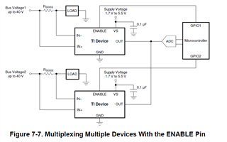
    4. Use two INA190s and split the dynamic range between them. You could even consider using the INA2191 (dual channel INA191). One interesting thing to consider is that the outputs of the these devices could be tied directly together since they can be enabled/disabled with ENABLE pin, which makes OUT go high-impedance. This allows you to use two amplifier to drive one ADC channel. The only thing to figure out is how to know when to disable one while enabling the other. 

    Best,

    Peter