Other Parts Discussed in Thread: LM7705, OPA2333, OPA333
Hello Team,
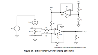
I want to measure the current through my load.
The current can vary from 0A to 1A.
The image below is the designed circuit.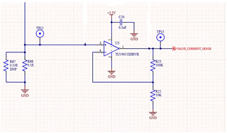
The resistor R87(0.33E) is not populated in the design.
The gain of the op-amp is set to 11.
The output of the op-amp is connected to the ADC of a controller.
The voltage at the output will be 0V to 1.1V for an input of 0V to 100mV.
The 0.1V will be a notable fraction of the drive voltage for the load.
1). How much smaller can we make the sense resistance before we run into issues like signal-to-noise ratio, etc?
2). We’ll need to compensate for the offset voltage in firmware. However the smaller the sense resistor offset voltage, the less compensation we’ll need.
3). Is it advisable to use zero drift amplifiers like OPA2333PIDSGT in my application?.
The GBW and SR of the OPA2333PIDSGT seem very low (minimum 1MHz and 1V/uS is needed respectively.)
However, a 100mE shunt resistor in the application note of OPA2333PIDSGT gives the same effect (compensation for the voltage) of TLV9051IDBVR in mu application
Please advise