This thread has been locked.

If you have a related question, please click the "Ask a related question" button in the top right corner. The newly created question will be automatically linked to this question.

INA4180: what kind of amplifier of hihe accuracy low side shunt current sense circuit

Part Number: INA4180
Other Parts Discussed in Thread: INA4181, INA185

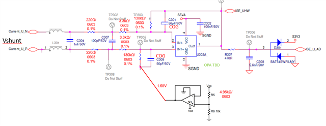
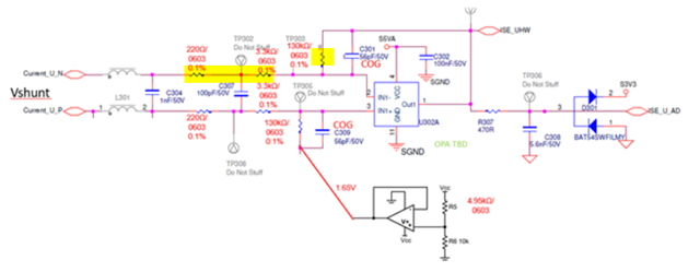
low side shunt current sense circuit is designed as shown as below, 

design spec: low side shunt current sense/ gain=37/ max frequency=30kHz/ as less 3 output in one package/ Vin=0V~0.037Vdc( Rshunt=0.2mOhm)/ Ta_max=85C / ADC full rating=3.3V

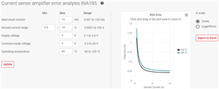
design target: output error < 0.5% during full input range (Vos can be neglected due to software calibration)

Question: 

1. what kind and part number of amplifier would be recommand ? Current-Sense Amplifier or operation amplifier? or other?

2. what is the advantage of using Current-Sense Amplifier(such as INA4180) vs operation amplifier?

  • I have to revise the Vin=0V~0.037Vdc to -0.037V~+0.037Vdc (Bi-direction input)

  • Hi Peter,

    what you have drawn is a differential amplifier with an improper connection of pseudo ground. The output of lower OPAmp should be connected to the cold end of lower 130k resistor.

    The disadvantage of this simple and low cost circuit is that it is only suited for low side measurements because the manufacturing tolerances, thermal drifts and long term drifts of feedback resistors will degrade the common mode rejection. So if you want to proceeed with this circuit then only in a low side application and with +/-0.1% toleranced resistors. C301 and C309 must also show a high balance. Because of that only low toleranced NP0 should be used.

    Also, the circuit should look fully symmetric at the input. So either you add another L301 which should be as identical as L301, or you install a common mode choke here, or you decrease the inductance to a low level or you omit an inductance at this place at all. With an unsymmetric input circuit the circuit doesn't work like a true differential amplifier with a high common mode rejection.

    Current sense amplifiers show an extremely high common mode rejection and are optimized for high side measurements but can also be used in low side applications, of course.

    Kai

  • Hi Kai

    Thanks for your suggestion. If there is any mistake in below revised circuit, please give your comment.

    Other question is 

    1. Is there any TI or online tool could quickly calculated the total error bsae on OPA circuit?

    2. What is the common mode volage could be in below circuit? is equal to  Vshunt or Vshunt+Vref(1.65V) ? or other?

  • Hi Peter,

    If calibration is employed and offset excluded, then I would look for something with gain error <0.5%, and with some margin in order to account for drift.

    INA4181 would be a great fit except that its GE spec is 1% max.

    I would recommend INA185, performance-wise I think it will be great for this application. Additionally, it is in a tiny SOT563 package at a great price.

    For low-side both Current Sense Amplifiers (CSA) and opamps (discrete solution) can work. The discrete solution can be flexible in gain/bandwidth configuration. The CSA is an integrated solution offering simplified schematic design and BOM reduction, with all resistors integrated into a single package. It brings advantages such as PCB area saving, excellent matching, excellent initial error and drift. Compete electrical specs can be found in all datasheets. Here is a high-level intro to CSA for your reference.

    We have online calculator for error estimate purpose. Here Vos is included and that’s why the % error picks up quickly at low current. But the high current region gives an idea what the % error is throughout when Vos is excluded.

    Regards, Guang

  • Hi Guang

    Thank for your reply.

    Is there any suggestion Part number for 4 output in one Package in this application ?

    and is there any option of CSA gain close to 37V/V? Otherwise, it need other amplifier or divider after CSA due to the fix gain (20 or 50 in INA185) .

    Besides, Could you give any suggestion or guildeline to design the resistance for OPA gain (like yellow mark resistor)?

    thanks.

  • Hi Peter,

    Besides, Could you give any suggestion or guildeline to design the resistance for OPA gain (like yellow mark resistor)?

    The circuit looks good so far. The resistor values of both input lines of differential amplifier must be identical which is the case in your circuit. And the values look reasonable as well.

    The cold end of C309 can also be connected to signal ground (0V instead of 1.65V).

    The gain is a bit high with 37V/V when your signal frequency range is 30kHz. When assuming a linearizing gain reserve of 20dB at 30kHz (-> open loop gain) you would need to take a 37V/V x 30kHz x 10 = 11MHz OPAmp. Using a lower gain would allow a bigger gain reserve. In this case you could decrease the 130k resistors a bit.

    Kai

  • you would need to take a 37V/V x 30kHz x 10 = 11MHz OPAmp

    Hi  Kai

    Thank for sharing.

    "37V/V*30kHz" should be the gain bandwidth (to compare with datasheet spec).

    I want to know why "37V/V*30kHz" should be multiplied by 10 ?

    Thank!

  • Hi Peter,

    On the topic of 4 channel CSA – INA4180/4181 are the only options for quad, we don’t have a corresponding one for INA185.

    Regarding gain – the closest match to 37 would be either 20 or 50.

    Sounds like you’re leaning toward a discrete solution. A 10x BW is desirable due to negligible impact on magnitude and phase delay, therefore the device output closely tracks differential input.

    Regards, Guang