This thread has been locked.

If you have a related question, please click the "Ask a related question" button in the top right corner. The newly created question will be automatically linked to this question.

INA303: IC Damage on power up the Board

Part Number: INA303

Hello,

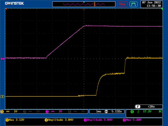
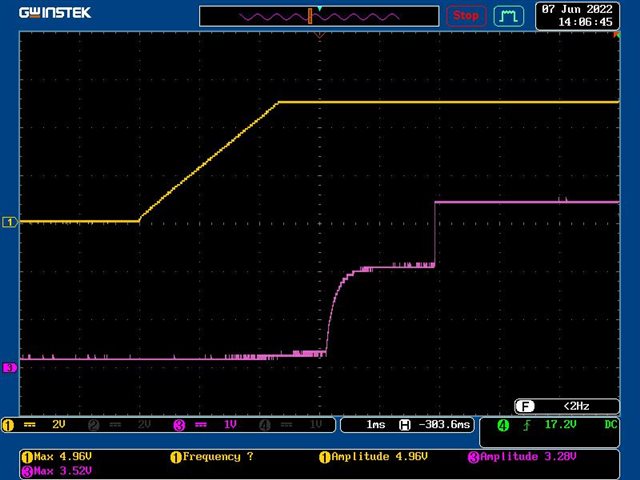
I am using INA303 device in the design for over current protection. We are observing the device getting damage when its powered and the Vs pin is showing short with GND.

Below is the schematic for the same,

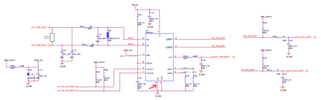
I do not see any circuit issue for the above. I notice only the NC pin is connected to GND. Will it cause any issue when NC pin is connected to GND.

Thanks for the support in advance.

Regards,

Anand M

  • Hi Anand,

    could be a soldering issue with unwanted short-circuits.

    But way more probable is that the INA303 got damaged because of a negative common mode input voltage.

    And it could be a supply voltage sequencing issue. Are you violating the absolute maximum ratings given in section 6.1 at any moment? Perhaps during power-down? Is the 3.3V staying longer at the INA303 than the 5V?

    Kai

  • Hey Anand,

    Connecting the NC pin to ground should not be causing damage. However, the power sequencing of the 5V and 3.3V rails could be a problem. The Max Abs Max ratings for essentially of the pins except for ALERT are Vs+0.3V. So if the 5V rail is being pulled to ground and the 3.3V rail is still on, then these pins could be exceeding this voltage rating, turning on internal ESD diodes causing damage.

    I would recommend starting with a non-damaged device and turning on 5V rail first and then 3.3V rail to see if device powers up properly, which it should. Additionally, using an oscilloscope to measure the input common-mode voltage at IN+/IN- pins to make sure there is not Abs Max violation here. The voltage at these pins do not need any special power sequencing; however, negative voltage transients to GND-0.3V  or positive transients to >40V can damage the device, so use the oscilloscope to verify this not happening during the power on.

    Sincerely,

    Peter

  • Hi Peter,

    I see the power sequence looks fine. I still do not understand why the IC fails immediately after the power ON.

    I probed on 3.3V pull voltage, 5V supply and differential voltage. Below are the waveforms:

    5V & 3V refence voltage

    5V and 3.3V pull up voltage:

    In my case the 5V supply settles first and then 3V and 3.3V. While probing differential voltage across sense, I see an spike of ~3Vpp for ~10us, but I would like to see if its really a voltage transient or probing issue.

    Is there any other thing which can cause such immediate failure.

    Regards,

    Anand M

  • Hey Anand,

    Did this 3Vpp spike happen during the power up? Or was this when you were probing the input lines after device was powered up?

    You may want to check the input pins' common-mode voltage (Vcm) on power up? Also, check for any ground loops or high impedances between the device ground node and system/source ground nodes. You could try using a differential probe to probe between INA303 GND pin and other ground return points on the board to make sure there is not a voltage > -300mV during the power up.

    Sincerely,

    Peter