Other Parts Discussed in Thread: TL431, LMV331, LM393LV, , LMV358
Good day!
Please, rate my first experience in analog circuitry.
The following task was released: to develop low cost a DC overload protection circuit (cut-off consumption more than 1.8A).
Explanations for the scheme:
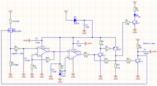
A low-pass filter was made on the R6,C5.
The OpAmp U1 amplifies the voltage drop across R9, then OpAmp U2 in the comparator mode compares with the reference voltage from U3 (TL431 is used as its voltage reference).
If the load is consumed more than the adjusted (R14 and R10), the latch is activated on transistors Q4 and Q3, next is opened Q5, the gate of Q2 is attracted to the ground, the load circuit is broken, LED D2 signals user about a malfunction.
The latch on Q4 and Q3 remains on until the main power is reconnected.
R5, C4 is delay line for gate Q2.
This need for exclude the case of a problem with the load when applying power. The power supply circuit of the protection circuit occurs through D1, C1.
After 3ms (time for R5, Q4), the load is switched on.
In the event of any problem with load, diode D1 prevents the voltage from flowing into the problematic section of the circuit and the stored energy in capacitor C1 goes to trigger the protection circuit.
I checked the functionality of this circuit on a breadboard.
What should I pay attention to?
This is my first experience in analog circuitry.
Dear community, please let me know your comments.