This thread has been locked.

If you have a related question, please click the "Ask a related question" button in the top right corner. The newly created question will be automatically linked to this question.

OPA210: PSpice model issue

Part Number: OPA210
Other Parts Discussed in Thread: LMV358, , TINA-TI, JFE150

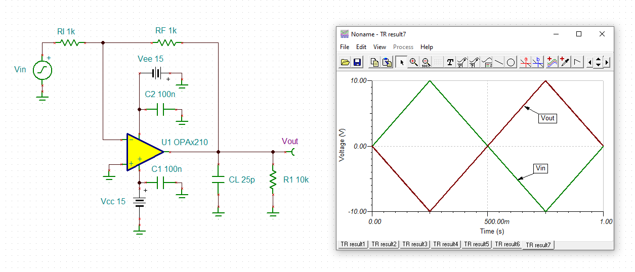
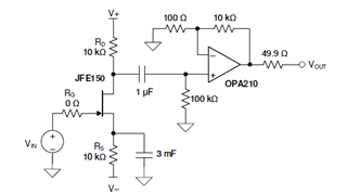
I am trying to simulate this amplifier using the provided PSpice model in Cadence 16.6.

I noticed that the circuit does not behave as expected, whereas replacing the OPA210 with a LMV358 leads to the expected results.

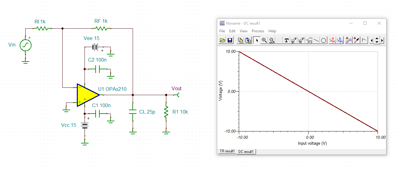
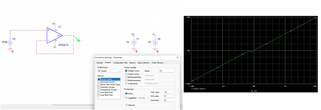
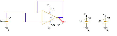
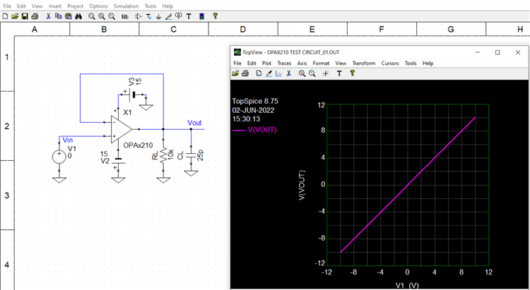
Initally I thought that my circuit was too complex, therefore I run 2 very simple DC sweep of the opamp input in unit gain with inverting and non-inverting configuration.

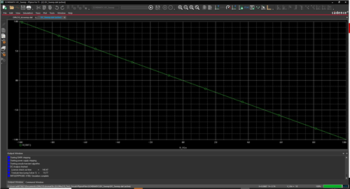
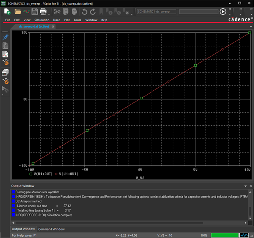
Results take time to be elaborated, which is already very suspicious for a DC sweep, but the plot (attached) is even more.

I would guess that the observed input/output characteristic is not normal...

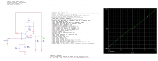
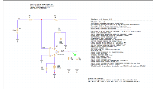
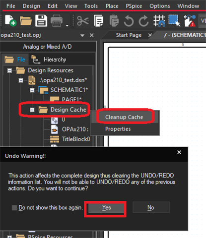
To avoid introducing any error, for the test above I have used the test project provided with the model, modifying only the routing of the wires.

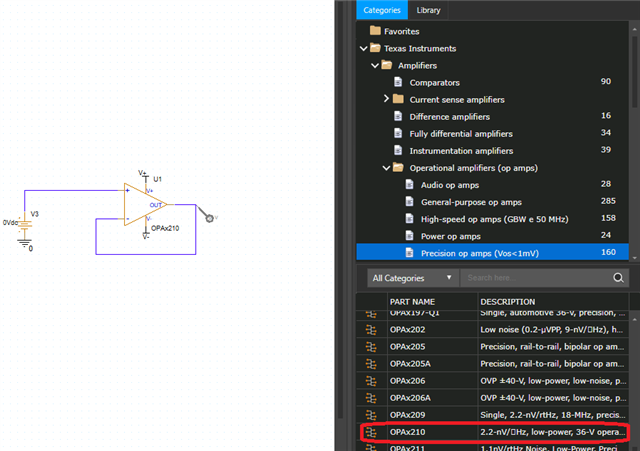
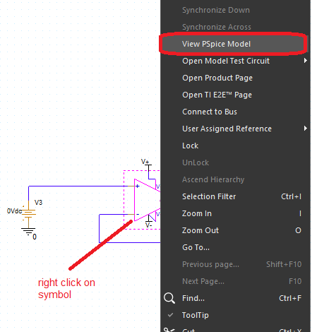
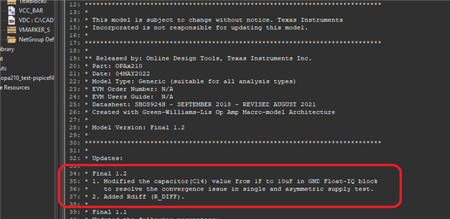
PS. I also noticed that the part used in the test file is not the same provided with the model: in the schematic V+ and V- are inverted with respect to those in OPAx210.OLB; also the drawing is different.

  • Hi Carlo,

    works for me in TINA-TI:

    carlo_opa210.TSC

    Kai

  • Hello,

    The team is on vacation. You can expect a reply by the end of the week. Thank you for your patience.

    Regards,

    Castrense

  • Hi Kai, thanks for your feedback. I guess there must be something wrong specifically with the PSpice model.

  • Hi Castrense, thank you for your message. Looking forward to a reply from the team.

  • Hi Carlo,

    I can import the lib-file into TINA-TI and this is also working. About the olb-file I cannot say anything.

    You could try to run a triangle wave of low frequency:

    Kai

  • Hello Carlo,

    The engineer in charge of this project will be back in office tomorrow.

    The model was tested with Cadence 17.4, while you are using Cadence 16.6.  When performing a DC sweep with TI PSPICE, the model appears to work.  Perhaps your simulation settings are different.  Can you share the project file to see if we can reproduce the issue?

    As Kai has mentioned, the model also works with TINA-TI.

    Thank you and Regards,

    Luis

  • Hi Luis, thanks for your reply. This is very weird.

    I guess that should not be any significant difference between Cadence 16.6 and 17.4.

    As test settings I used the default ones, as in the model file there is no note suggesting the use of specific settings. Furthermore, I browsed through the settings in the test file provided and I did not see anything different from default.

    What I noticed, however, is that the component used in TI test project is not the same provided in the OLB file in the same folder.

    I will generate a clean test project and share with you as soon as I am back in the office

  • HI Carlo,

    Thank you for the update.  We will wait for your simulation/project files once available to reproduce/debug the issue.

    Kind Regards,

    Luis

  • Hi Luis,

    I simulated a DC sweep of a simple buffer, from which you can see an offset for negative voltage and a discontinuity in zero.

    Furthermore, this kind of simulation is typically executed in a fraction of second, but with this model it takes almost 10 seconds.

    Please find attached the test project.

    opa210_test.rar

  • HI Carlo,

    I discussed with the Engineer that supports the PSPICE model development.  It appears that your project may be simulating/associated with a previous version of the model that had convergence issues; this explains why the schematic shows the old schematic symbol / OLB file.    

    1) When using TI-PSPICE, in order to update the models, you could re-install the whole library of TI PSPICE models.  Alternatively, you could open/close the PSPICE for TI software a few times to trigger automatic updates.  The session log window should show below line as a comment whenever automatic update happens: "INFO(ORCAP-2441): PSpice and Capture libraries updated. Metadata update is in progress."

    You may also see a notification as shown below (unless the dialog has been turned off), press OK:

    2) Once the process has been completed, you may need to delete all instances of OPAx210 symbol(s) across all the schematics within the project. Also, navigate to the ‘Design Cache’ folder at the left side of the screen, and click on Cleanup Cache, a dialog may appear, click "Yes":

    3)   Place the new OPAx210 symbol/model combo.  Navigate to top menu: Place --> Part -->Texas Instruments --> Operational Amplifiers (op amsp)--> Precision op amps (Vos<1mV)  and find "OPAx210". 

    To verify/confirm that you are loading/simulating the latest version, Right-click in the op-amp symbol, and click on view PSpice Model.  The contents of the model file should display "Final 1.2", and the symbol should display as below.


    Update 6-1-22:  Left click on OPAx210 symbol, under "Graphic" property, select "OPAx210.Convert." If the symbol changes, ensure the op-amp has negative feedback:

    After I worked in your project and updated to the latest model version, the DC Sweep simulation results are correct, as shown on the previous post.

    Let me know if issues persist.  

    Thank you and Regards,

    Luis

  • Hi Luis,

    thank you for your reply.

    The difference I noticed in the symbol is now clearly explained by the selection of "OPAx210.Convert." in the Graphic property.

    Unfortunately, however, that did not solve my issue, because the model I'm using is already the last (Final 1.2).

    As I am not using TI-PSpice libraries, I did not have an OPA210 symbol that could be updated. I just downloaded the OPAx210 PSpice Model (Rev. B) from https://www.ti.com/lit/zip/sbomat3 and manually added the provided library symbol (OLB) and model (LIB).

    It is the first time that I see the solver struggling for a DC sweep with a single opamp. Every simulation step requires:

    Starting GMIN stepping
    Starting power supply stepping
    Starting pseudo-transient algorithm

    Are you using any specific simulation setting to improve convergence?

  • HI Carlo,

    I downloaded PSPICE for TI and the OPAx210 PSpice Model (Rev. B) from the OPA210 product page without any modifications. On my side, it appears to work without special settings or modifications, but I can confirm that I see the simulation on the output window requires the below to converge:

    Starting GMIN stepping
    Starting power supply stepping
    Starting pseudo-transient algorithm

    On my side, it converges on both the inverting and non-inverting circuit to the correct result. Despite experiments, I have not been able to reproduce yet a case where it provides the wrong result that you see above. I also discussed and simulated on a second PC with the team that develops this PSPICE model, unable to immediately reproduce.

    I have referred this query to the applications engineer responsible for the OPAx210 device, and to the team involved with the PSPICE model (yesterday). Once or if they are able to reproduce the issue, they probably be able to debug and reply back with a solution.  

    Thank you and Regards,

    Luis

  • Hi Carlo,

    I simulated now in both PSPICE for TI and Cadence 17.4 on both inverting and non-inverting configuration without issues; the engineer involved in the model development was also not able to reproduce the issue.

    For reference, under simulation setting options, on both PSPICE for TI and Cadence 17.4, the settings are as default as shown below.  Please confirm your settings are the same.  

    If they are the same, this is well beyond my knowledge since I can't reproduce, and I will let Thomas Kuehl and/or the PSPICE team follow up with you directly,

    Thank you and Regards,

    Luis

  • Hi Carlo,

    Extensive efforts involving engineers from our applications and and modeling teams have been made to reproduce the OPA210 PSPICE for TI anomaly you describe. The OPA210 model readily and quickly simulates using PSPICE for TI, Cadence 17.4 and TINA-TI as mentioned previously. Additionally, I just tested the model using another PSpice compatible simulator TopSpice.

    The OPA210 model easily and quickly simulates without incident with this simulator as well. The results are seen below for the OPA210 configured as a follower with a -10 V to +10 V DC input sweep applied. I tried several other configurations and analyses and the model readily produced the expected results nearly instantaneously for each simulation performed.

    Our findings suggest there is possibly something not correct with your PSPICE for TI installation, or there is a setting that is causing the different results. Do you have access to another computer that has a PSPICE for TI installation that you can load and try your circuit? Or better yet, access to another computer where you can do a fresh PSPICE for TI installation and then try your simulation circuit again?

    Regards, Thomas

    Precision Amplifiers Applications Engineering

  • Hi Thomas,

    I truly appreciate the efforts you and your team put in reproducing the issue.

    I honestly don't know what to think, I have been using Cadence 16.6 for several years now without ever experiencing any similar problems. I have a wide collection of downloaded PSpice models from TI and other manufacturer that work without any issue.

    I wonder whether any significant change was introduced in the PSpice solver between Cadence 16 and 17. Unfortunately, I don't have any newer Cadence installation available to test the circuit.

    As I don't have my working laptop with me at the moment, I cannot compare the simulation parameters as Luis suggested. But it will be the first thing I will do on Monday.

    Eventually, my final goal was to evaluate the noise floor in a circuit architecture based on JFE150 and OPA210, similar to the one in the image below but wihtout ac coupling and feedback loop closed on the JFET source.

    The JFET model provided by TI works without any problem, but when I add the OPA210 things become odd. The simulation always converge, but clearly result are not reliable as the output stage increasingly attenuates for increasing values of the opamp feedback resistor. Replacing the OPA210 with any other opamp solves the issue and the circuit behave as expected.

    Considering your feedbacks, for as intriguing it would be to understand what is causing the issue, I actually need to carry out this simulation quickly. Can you please suggest an alternative tool to perform noise analysis? Does PSpice for TI support it?

  • Hi Carlo,

    keep in mind that all the TI's models are optimized for TINA-TI. So if there are any doubts, run the simulation in TINA-TI, at least the circuit section containing the OPAmp making issues. TINA-TI is free and super simple compared to many other simulators Relaxed

    Kai

  • Hi Carlo,

    Understanding that you observed the OPAx210 DC sweep issue on your end, have you attempted to run any AC or noise simulations on the simple amplifier circuits using PSPICE for TI?

    Kai mentions TINA-TI and that simulator is readily available online from TI. Its extremely easy to use and has about a 15 minute learning curve. You may find that gets your project moving faster than spending more time and effort to figure out the particular PSPICE for TI simulation issue causing the anomaly.

    What Kai mentions about the TI op amp models being optimized for TINA-TI was more applicable when we first started using that simulator about 15 years ago. However, more than 5 years ago we started an internal project to evaluate our models using several PSPICE based simulators and make sure that we received equivalent results from each of them. You really should receive the same results from our modern op amp models when used with the popular PSPICE based simulators.

    Regards, Thomas

    Precision Amplifiers Applications Engineering