This thread has been locked.

If you have a related question, please click the "Ask a related question" button in the top right corner. The newly created question will be automatically linked to this question.

OPA333: OPA333

Part Number: OPA333
Other Parts Discussed in Thread: TIDA-00879

Hello,


I have a few questions for the TIDA-00879 Analog Front End section.

1-) What is the formula for calculating the voltage divider resistance values so critical in the TIDA-00879 reference design chart?

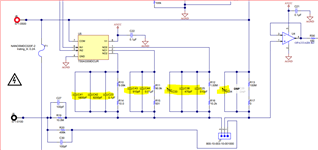
2-) A capacitor is connected in parallel to the voltage divider resistors and a fixed 470pF and 510pF are connected to some voltage divider resistors together with a parallel adjusted capacitor. How are these capacitor values calculated? I marked the capacitors with yellow color in the attached picture.

Thanks,

Arge

  • Hi Arge,

    hhm, isn't this self explaining? These are frequency compensated voltage dividers. R19 and R13 set the pace with a division factor of 1.1. The other voltage dividers perform division factors of 11, 110 and 1100, all differening from each other by a factor of ten. Becaues of being a simple voltage divider the lower resistor of the voltage divider follows the rule:

    R_lower = 10M / (factor - 1) 

    with R_upper = 10M.

    ->

    1.1: R_lower = 10M / 0.1

    11: R_lower = 10M / 10

    110: R_lower = 10M / 109

    1100: R_lower = 10M / 1099

    And because the 100M is in parallel to all "R_lower" the following resistors have to be mounted in parallel to the 100M:

    R_lower / (1 - R_lower / 100M )

    ->

    1.1: -

    11: 1010101R

    110: 91827.36R

    1100: 9100.009R

    And the frequency compensation is done by setting the cap in parallel to "R_lower" to give a time constant of R19 x C27 = 10M x 100p x sec = 1msec.

    Kai

  • Arge,

    If you need further assistance, please let us know.