This thread has been locked.

If you have a related question, please click the "Ask a related question" button in the top right corner. The newly created question will be automatically linked to this question.

OPA827: About temperature rise of parts

Part Number: OPA827

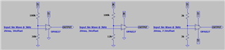
A 3kHz SIN wave is input in an environment with an ambient temperature of 25 degrees.
(1) When used with a single power supply (+ 15V)
(2) When used with a single power supply (+ 30V)
(3) When used with both power supplies (± 15V)
How much will the temperature rise in the three patterns?

I tried to measure the parts alone,
Single power supply (+ 15V) is 37 ℃
Single power supply (+ 30V) is 50 ℃
Both power supplies (± 15V) are 50 ℃
Has risen to.

Is this temperature rise normal?

  • Hi Masato,

    you want to use this expensive, low-noise and high-precision OPA827 as simple comparator?

    Kai

  • Hi Masato-san,

    The schematics you posted are all comparator circuits. As Kai suggested, it will be better to use comparators for the application. The above OPA827 circuits are operating in saturating states and it will consume a lot more more than linear operation, hence the temperature rise, especially the application is operating at higher voltage power rails. The application's input is 3kHz sinusoidal signals and the square waves are generated at OPA827's output (only two states are generated at the output of the saturated OPA827, depending on your supply rails). 

    Below is a video clip that talks about the pros and cons for the application. 

    https://training.ti.com/jp/ti-precision-labs-comparators-pros-and-cons-using-op-amp-comparator

    If you have additional questions, please let us know. 

    Best,

    Raymond

  • In full agreement that you should NOT use OPA827 op amp as a comparator.  But to answer your question about the temperature rise, what you see makes sense.

    If you look at the thermal resistance of OPA827 (DGK) below, it is 180 [C/W]. With 3kHz signal and no load, the average power dissipation inside OPA827 is simply: P=IQ*Vss where IQ is a quiescent current (4.8mA) and Vss is a total supply voltage: Vss=15V for +15V single supply BUT Vss=30V for +30V single supply and for +/-15V.

    Thus, you may calculate the temperature increase in the following way:

    Single power supply (+ 15V),  Tj = Ta + P*Rϴja = 25C + 4.8mA*15V*180[C/W] = 25C + 13C = 38 ℃  (you claim 37 ℃)
    Single power supply (+ 30V),  Tj = Ta + P*Rϴja = 25C + 4.8mA*30V*180[C/W] = 25C + 26C = 51 ℃  (you claim 50 ℃)
    Both power supplies (± 15V),  Tj = Ta + P*Rϴja = 25C + 4.8mA*30V*180[C/W] = 25C + 26C = 51 ℃  (you claim 50 ℃)

    The above numbers match what you see.  For more info, how to calculate AC power dissipation, please review following video:

    https://training.ti.com/ti-precision-labs-op-amps-power-and-temperature?context=1139747-1139745-14685-1138799-607342

  • Hi Kai-san,
    Hi Raymond Zhang1-san,
    Hi Marek Lis-san,
    Thank you everyone for your reply!
    I didn't know where to reply, so I'll post it here.

    Oh, I'm sorry.
    I didn't write the point.
    In advance, I decided to do a temperature test with a simple comparator circuit.
    Actually, we plan to operate it as a non-inverting amplifier circuit.
    The measured temperature is the surface temperature of the package.
    There was another part that was not OPA827 that exceeded 100 ° C, and it was a damaged part.
    This OPA827 is also feverish and I couldn't tell if it was normal or broken, so I asked.

    I will read the explanations and videos that you have introduced.
    Thank you.

  • Hi Masato-san,

    I couldn't tell if it was normal or broken, so I asked.

    The quiescent current in OPA827 may go up to 6mA/Channel at an elevated temperature. The temperature rises are expected per the voltage rails and configuration from Marek's temperature rise estimation.  

    You may select comparators and or pick other low quiesecent current op amps for the use as comparator. Of course, I do not recommend the latter configuration, even though it may work out ok sometimes. 

    Best,

    Raymond  

  • Hi Raymond-san,

    As you say, when I changed to an IC with lower current consumption, the heat generation subsided.
    It seems that the temperature problem can be solved by choosing an IC that consumes less current.
    I'm really thankful to you.