This thread has been locked.

If you have a related question, please click the "Ask a related question" button in the top right corner. The newly created question will be automatically linked to this question.

OPA277: Improved Howland Current Source switching C-R load - howto protect the OPAMP from floating output / stability

Part Number: OPA277
Other Parts Discussed in Thread: TINA-TI, OPA551, OPA593

Hi all.

For a medical sensor testing facility I need to inject a precise "pulsed" current into the sensor (merely modeled as a resistive load) for a given amount of time. 

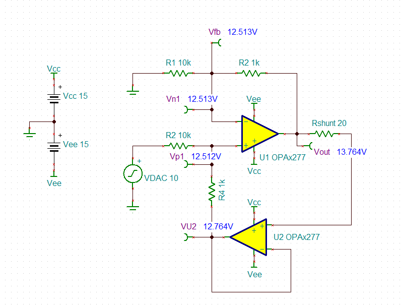
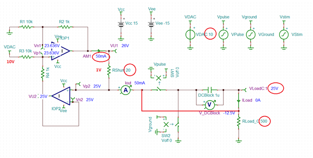
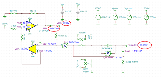
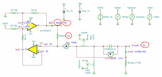
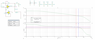
That's why I was thinking of a Howland Current pump with the OPA277.

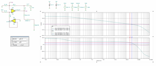
I can theoretically control the current precisely via the voltage applied at its input. Here the TINA-TI simluation:

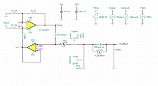
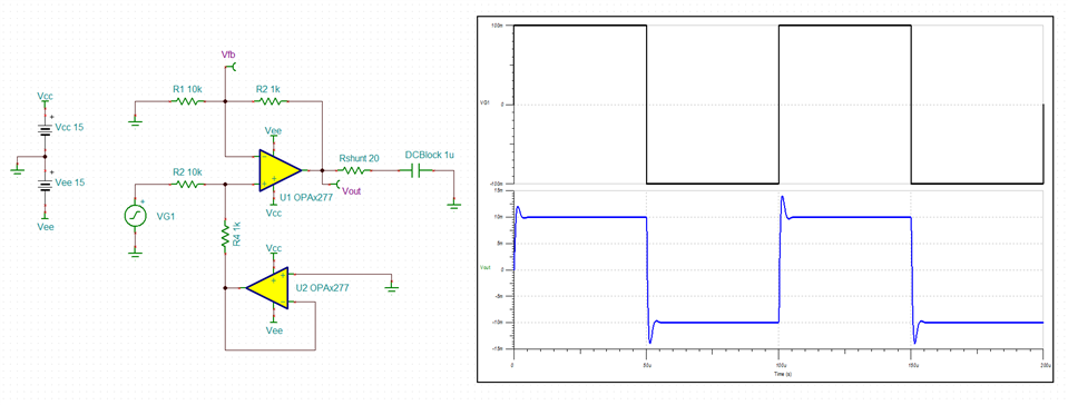
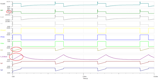
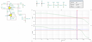
A DC blocking capacitor at the output of the opamp before the pure resistive is used so forming a C-R circuit (a high pass filter).

The stimulation is performed in two phases:

- Pulse phase (lasting 600us): where the load is connected to the opamp via the DC Block capacitor injecting the current typically 10mA-20mA.

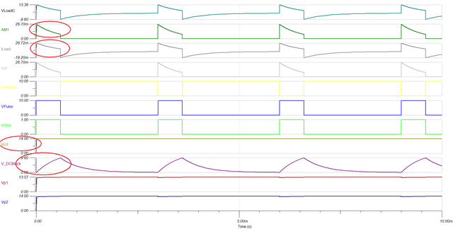
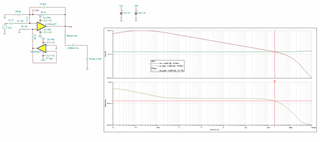
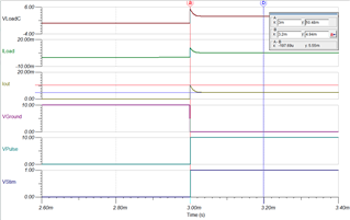
- Ground phase (lasting 2,4ms): the load disconnects from the opamp and shorts to ground. therefore the charge accumulated into the DC capacitor flows back into the load in the opposite direction until its complete discharge, avoiding any net charge accumulated into the load ( in reality the sensor) during every cycle. That is graphed on the photo attached where I have used two pulsed square waves (Vpulse and Vground) to activate the relative switches.

You can see in the figure the first graph Iload - the current that flows back and forth into the load. 

Now the questions:

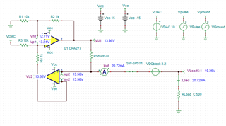
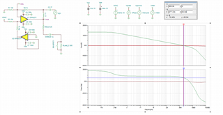
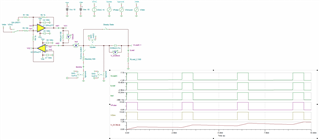
1. Am I secure during the ground phase to let the output of the OPAMP floating and then switching it back to the load? I'm afraid not: there will be for sure on a real PCB parasitic inductances, but I don't know how to perform such a protection. what is the best way to protect the output stage of the opamp? should I switch the opamp to a dummy resistor during the ground phase?

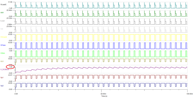
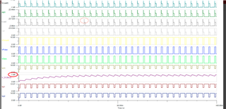
I can see spikes on the output of the OPAMP: the things get worser if I reduce the current injected to 5mA, i have huge current spikes of 10mA on the output during the reconnection of the load.

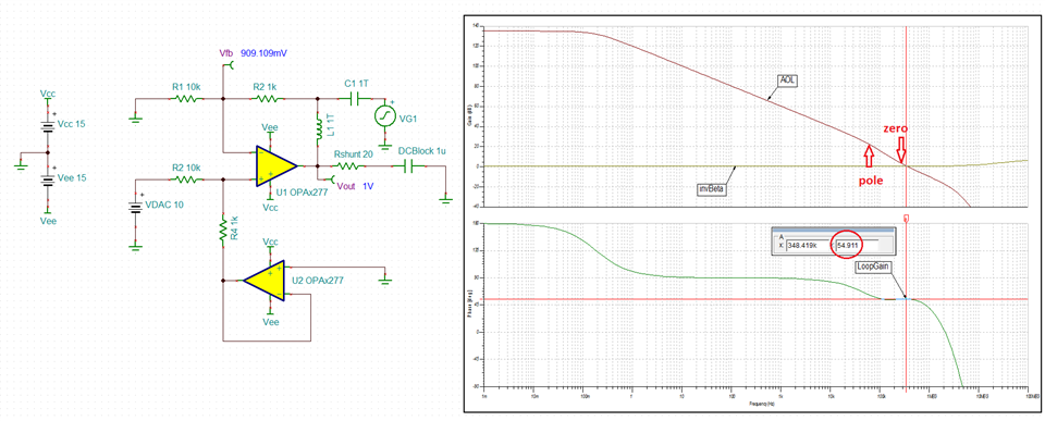
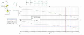
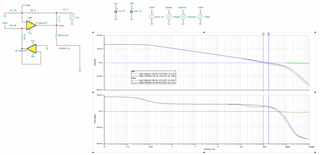
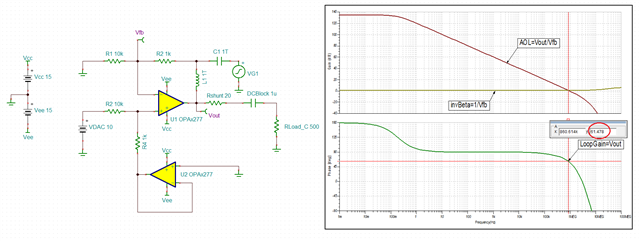
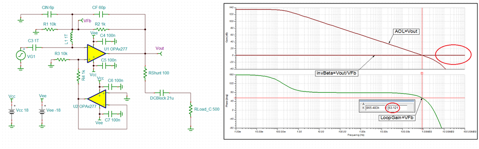
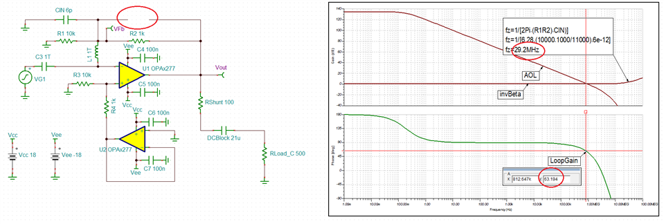
2. How to calculate the stability of the circuit with this typology of loads?

I mean, having studied the Ti precision Lab theory stability chapter there is always mention of capacitive loads connected in parallel that introduces poles, not in serie one. So how to perform such an analysis?

My AC analysis is a little bit naive. Since the load resistance may vary from 400 to 1,2k I would like to be sure about the correct phase margin. But don't know where to start. Where have I to open the OPAMP loop?

Have already read the suggestion from Tim Green here: https://e2e.ti.com/support/amplifiers-group/amplifiers/f/amplifiers-forum/739959/tina-spice-ina133-tips-to-carry-out-stability-analysis-for-improved-howland-current-source but don't know where to start.

Thank You for any help in advice, 

  Stefano

  • Hi Stefano,

    Below please see my answers:

    1. During Ground phase  DCBlock capacitor becomes completely discharged and therefore PCB parasitics do not matter.  Without the current flow there is NO possibility that switching load back-in could potentially drive the output beyond its rails.  Also, during Ground phase the op amp output does NOT float but rather collapses close to positive rail ~(V+)-1.5V - see below.  Thus, the current spike you see is caused by the output overload recovery from a non-linear condition; therefore,  I do NOT see possibility of damage since the maximum output current will be limited to 35mA by the internal short-circuit protection circuitry.

    2. The 1uF DCBlock cap is connected in series with 20ohm Rshut (Riso) resistor.  Thus, (Ro+Rshunt)||1uF forms a pole while Rshunt||1uF forms a cancelling zero - see below.

    However, in order to simulate the stability of the circuit, you need to place it in a linear operation - I have done this by grounding the input of U2 - see below.  Running AC stability analysis shows the phase margin of ~55 degrees whereas the minimum recommended is 45 degrees. 

    Running a small-signal transient simulation showing 20% (4mV/20mV*100%) overshoot while max recommended is 25%.  This confirms the stable operation of the circuit.

    For your convenience, below I have attached the Tina-TI stability schematics.

    OPA277 AC Stability.TSC

    OPA277 Transient Stability.TSC

  • Marek. Really grateful, I appreciate it a lot. Thank You so much.

    I was editing my post adding TINA-TI schematic when I saw yours: here it is:

    Improved HCP_OPA277-Both_phases.TSC

    You are completely right. My fault not to have seen before the return path when load disconnected. Sorry

    What happens to the OPAMP output if, due to increasing blocking capacitance, the DC Block is not fully discharged? I mean often in reality you have to put a switchable bank of selectable 1uF - 11uF - 21uF capacitor that often reaches, after a initial transient, stabile charged/discharged values. The important is that the net charge that passes back and forth on the load is equal to zero. Please see here a simulation of a 21uF cap:

    So we are in ground phase: both outputs of the OPAMPs have reached their Vout swing max.  U1 is saturated since V+ not equal to V-  (half a volt difference).

    During the next pulse phase the opamp sees at its output a semi-loaded cap. Does it really matter?

    If we suppose that the wires that connects to the sensor and the traces of the PCB could have an inductance of 100uH could this leave to instabilty?

    How can I simulate it?

    For the part regarding AC analysis I have new born questions but I want to study by myself before asking dumb/obvious questions. Sorry for the long post.

    and thanks again.

    Stefano

  • Hi Stefano,

    I see VU1 and VP2 being at about 14V all the time. So why are you using a Howland current pump?

    Kai

  • Stefano,

    I believe the whole idea behind using Howland pump is to control the current charging the DCBlock cap so together with the timing of Vpulse/Vground clock you can achieve desired steady state voltage across the cap.  With VDAC of 10V the output voltage across Rshunt is 1V, which fixes the output current AM1=1V/20ohm=50mA  - see below. Even if the OPA277 could deliver the 50mA (which it cannot since Isc is 35mA), this would drive the VLoadC to 25V (50mA*500ohm).  Thus, in order for the circuit to work linearly VU1 would need to be able to go to 25V+1V=26V (unlikely on 15V supply).  

    All of this causes OPA277 to saturate at the positive - see below Vout at 13.96V and AM1 current of 26mA instead of 50mA. 

    All of these cause ILoad to decrease over time resulting in a non-linear charging of V_DCBlock cap - see below.

    Therefore, in order to assure that the circuit works linearly, you need to decrease VDAC or increase Rshunt. Using Rshunt of 100ohm results in a constant ILoad current of 10mA during Vpulse - see below.

    Running transient analysis confirms a constant 10mA ILoad charges DCBloack cap, thus resulting in a linear voltage change across it - see below.

    Increasing the DCBlock cap to 21uF while using Rshunt of 100ohm results in the steady-state voltage across it of 1.48V - see below.

    All in all, you need to decide what the end goal here is and accordingly modify the circuit in the way that it meets the timing needs while operating linearly - you cannot allow tOPA277 output to get within 1.5V below its rail.  This is the only way to make sure that the results will be as predicted by the simulation.

    Improved HCP_OPA277-Both_phases ML.TSC

  • Ciao Stefano,

    I have another question:

    Why so complicated with the DCblock capacitor in series with the sensor? Why not just using a Howland current pump sourcing a simple and harmless DC current? Or even using only a simple reference voltage in combination with a suited current limiting resistor?

    Kai

  • Hi. I really appreciate the way you nail down all the critical aspects I cannot see yet. That helps me deconstruct all my wrong believes in order to build a solid understanding. Thank You.

    That said let’s go in order.

    1. The choice of a Howland current pump that Kai asks (thanks for your support even in the other post), is that it is a popular high performance, voltage-controlled current pump, which can both sink and source precise amounts of current and provide high output impedance as well as high frequency bandwidth.

    One main requirement of the testing facility is to achieve a “pulsed” current injection in the -35mA to 35mA range over a load that can vary its resistance during test from 400 to 1,5k (manly it is 500 ohm) still requiring a constant current.

    So that’s why my original idea was to steer the HCP through a DAC by digitally controlling a negative/positive voltage applied on its input (let’s for now neglect the OPAMP saturation problem for the OPA277).

    Choosing a high current OPAMP like the OPA551, or the new OPA593 as Kai and Thomas suggested here could resolve this issue with the cost of adding a higher supply voltage and use of high voltage multiplexers and analog switches.

    Otherwise I could choose a 0-35mA range and literally switch and reverse the load with an H-bridge. This is an option and that could also help me with the 100V total compliance voltage problem but it also opens a bigger scenario adding more complexity to the circuit.

    2. The use of a DC Blocking capacitor aims to perform what’s called the Charge Balancing Process: principally, whenever current during the test is conducted over the load immersed into a conducting solution, chemical processes take place at the interface. By applying a large potential (that can reach as seen 100 Vpp) over a longer period of time, charge is massively exchanged over the electrode and strong currents flow which cause electrolysis, pH change, electrode dissolution. In order to avoid these irreversible electrochemical reactions, the stimulating current pulse is typically balanced and biphasic, which ensures that no net charge appears at the electrode after each stimulation cycle and the electrochemical processes are balanced to prevent net dc-currents. That’s why a sink/source current generator is needed that pushes and pulls same amount of current; but in reality 1%-5% of mismatch of the current pulses has to be taken into account so he most common solution is to insert a large, dc blocking capacitor in series with the stimulation electrode, which guarantees that no dc-currents can flow to the electrode over time. Nonetheless, regular discharge of the blocking capacitor is necessary in order to avoid saturation due to dc-current integration and consequently reduced output voltage compliance of the stimulator.

    By the way is there a real method to get rid of these current spikes?

    Now regarding the AC stability I have following questions ( sorry for the verbiage...):

    1. Using the OPA277 (builtin in TINA-TI) and the OPAx277 (Reference Design based on Green-Williams-Lis Pspice simulation model) TINA-TI models led me to different bode plots:

    OPA277

    OPAx277

    Which one should I take it for references? I suppose the latter one since the OPA277 just gives me a 90 degree phase margin - too generous to be true I think.

    2.In your simulation You provided NOT considering the Rload of 500 ohm, did you put yourself in the worst case scenario (also lower phase margin)? I mean adding the Rload in series, would only result in increasing the Aol beta frequency by pushing the pole further away in frequency since the canceling zero formed by (Rshunt || DCB) remains there?


    3. By simply changing the Rshunt resistance value from 20 to 100 in your simulation I noticed that the phase margin for Rshunt = 20 ohm lays on a flat curve while the other on a steeper curve: does this means that it could potentially lead to more instability?

    Is the goal to tweak the external component values in order to let it stay on a curve as flat as possible? 

    4. I wanted to investigate how stability is affected by the change of the DCBlocking value so I swept it. Why in the world are the Bode plots apparently similar using a sweep of DCBlocking caps from 1uF to 21uf at least one order of magnitude different one from another? Shouldn't at least the zero change?Am I missing something?

    Here the simulation I have used:

    Improved HCP_OPAx277-AC Stability_Rs100-Rl500-DCB1sweep21u.TSC

    I honestly am really sorry for all this questions, so much open questions in my head... hope you all won't get bored..

    Thank You again.

    Sincerely

  • Ciao Stefano,

    no reason to apologize. Solving tricky problems is just fun Relaxed

    Kai

  • Stefano,

    Please see my answers below:

    1. Using the OPA277 (builtin in TINA-TI) and the OPAx277 (Reference Design based on Green-Williams-Lis Pspice simulation model) TINA-TI models led me to different bode plots.

    Correct. This is the reason why we have created Green-Williams-Lis model - OPAx277 is a modern behavioral macro-model (GWL) while OPA277 uses an old transistor-level architecture created back in 1999 that do not properly account for the variation of open-loop output impedance (Zo) over frequency that is the most critical factor behind proper simulation of AC stability  - please do NOT use it.

    2.In your simulation You provided NOT considering the Rload of 500 ohm, did you put yourself in the worst case scenario (also lower phase margin)? I mean adding the Rload in series, would only result in increasing the Aol beta by pushing the pole further away in frequency since the canceling zero formed by (Rshunt || DCB) remains there?

    Loading the output with 500ohm increases the current in the output stage resulting in the decreasing Zo - this pushes the second pole into a higher frequency, fp=1/(2Pi*Zo*C_DCBlock), improving the phase margin. Please make sure you do the post-processing of AOL=Vout/Vfb and invBeta=1/Vfb - see below.

    3. By simply changing the Rshunt resistance value from 20 to 100 in your simulation I noticed that the phase margin for Rshunt = 20 ohm lays on a flat curve while the other on a steeper curve: does this means that it could potentially lead to more instability?

    Since fp=1/[2Pi*(Ro+Rshunt)] and fz=1/[1/(2Pi*Rshunt)], if Ro>>Rshunt there is a large separation between the pole and zero frequency resulting in a phase dip whereas in case of Ro<<Rshunt, there is hardly any difference between fp and fz  so the phase does not have time to dip before zero cancels the effect of the pole.

    Is the goal to tweak the external component values in order to let it stay on a curve as flat as possible?

    The goal of Rshunt (Riso resistor) is to bring fp and fz close together in frequency in order to eliminate the phase dipping.  Please review stability section of TI Precision Labs - see following link:

    https://training.ti.com/ti-precision-labs-op-amps-stability-introduction?context=1139747-1139745-14685-1138805-13848

    I wanted to investigate how stability is affected by the change of the DCBlocking value so I swept it. Why in the world are the Bode plots apparently similar using a sweep of DCBlocking caps from 1uF to 21uf at least one order of magnitude different one from another? Shouldn't at least the zero change?Am I missing something?

    The fp and fz both change by 21x and thus the phase margin is unaffected. As discussed above, with Rshunt of 100ohm fp and fz are close together cancelling each other so the circuit is immune to the change in load capacitance. This is the whole reason for adding Rshunt (Riso) in series with output load in order to stabilize the circuit regardless of Cload.  Even with Rshunt of just 20ohm, fz=~4*fp and thus the circuit maintains stability by keeping phase margin above 45 degrees. 

  • Hi Stefano,

    By the way is there a real method to get rid of these current spikes?

    When SW1 opens, the current can no longer flow. The output of Howland current pump tries to correct this and increases its output voltage in the hope to make the zero current increase again. But it can not of course and goes into saturation (->14V).

    When SW1 closes again, the output of Howland current pump is still in saturation and needs some time to establish regulation. During this period the current spike appears. When the output of Howland current pump has recovered from saturation, the current spike disappears.

    The current spike can be prevented or at least diminished when you switch a dummy load to the output of Howland current pump whenever the switch SW1 opens. This would prevent the output of Howland current pump from going into saturation.

    Kai

  • Hi Stefano,

    2. The use of a DC Blocking capacitor aims to perform what’s called the Charge Balancing Process: principally, whenever current during the test is conducted over the load immersed into a conducting solution, chemical processes take place at the interface. By applying a large potential (that can reach as seen 100 Vpp) over a longer period of time, charge is massively exchanged over the electrode and strong currents flow which cause electrolysis, pH change, electrode dissolution. In order to avoid these irreversible electrochemical reactions, the stimulating current pulse is typically balanced and biphasic, which ensures that no net charge appears at the electrode after each stimulation cycle and the electrochemical processes are balanced to prevent net dc-currents. That’s why a sink/source current generator is needed that pushes and pulls same amount of current; but in reality 1%-5% of mismatch of the current pulses has to be taken into account so he most common solution is to insert a large, dc blocking capacitor in series with the stimulation electrode, which guarantees that no dc-currents can flow to the electrode over time. Nonetheless, regular discharge of the blocking capacitor is necessary in order to avoid saturation due to dc-current integration and consequently reduced output voltage compliance of the stimulator.

    I fully understand that you don't want to have net DC current flowing through your sensor because of the danger of starting chemical processes. But this is exactly what happens during the charge-up period of your "DCblock" capacitor, at the begin of your measurement.

    Wouldn't it be better to drive a true AC current through the sensor? You can still add a "DCblock" capacitor to prevent longer lasting DC currents from flowing through your sensor in the case that the measuring scheme runs faulty.

    You would have to drive the input of Howland current pump by a true AC signal (symmetrical square wave) then.

    Kai

  • No words to say thank You so much. You have made bright light in the darkness of my voyage...

    Grazie

  • Kai. You were right. I did not think on such a issue. Infact running a simulation with a dummy load attached mitigated the issue on output of opamp and solved them on the load (totally disappeared).

    I was also thinking, since I need to get sink & source phase and so provide negative and positive voltage, to feed the opamp with a square wave in phase with the one I use to switch to ground the load. Theoretically during ground phase the opamp should have 0V on his input so it does not saturate.

    With a perfect timing I should overcome this even if I have to study the slew rate...

    Thanks again

  • Hi Kai.

    Thanks for pointing this out.  Hope I understood what you said, see if it's the case. One single test can usually last for weeks/months. Once fired there is no need to stop them and let the capacitor reach again the steady-state voltage level that is reached in less than 25ms causing a net charge to reach the load.

    Once the test has ended the dc capacitor is completely discharged.

    When you say "drive a tue AC current" do you mean driving the load with the two phases (sink and source) in which the current flow first in one direction and then the other?

    Best regards


  • Marek.. I have one last question (Doh..) hope you have already some patience left.

    I wanted, in order to close the circle, to solve the real-world issue regarding the compensation for parasitic input capacitance at the inverting opamp input using a feedback capacitance. I have followed the part 6 of the op-amp stability series. I have tried to get some results by adding the CF capacitance that I have calculated to be approx 60pF but I don't know again where to break the loop on the inverting input.

    I am getting horrible bode-plots as shown below. have already tried for a couple of hours without effort.

    Could you please help me nailing it down? I would appreciate it.

    Improved HCP_OPAX277-AC StabilityMultipleFBLoop.TSC

    My goal is to implement the lead-lag compensation at the input terminal of opamp1 since I have seen this is a common in howland topology.

    Thanks again alot

  • Below please see the setup for simulating of the phase margin with VG1 source at the input - the circuit has phase margin of 63 degrees - very stable.

    Having said that, you do NOT need CF to stabilize the circuit - without it the phase margin remains at 63 degrees-see below.  This is because zero, fz, occurs at 29.2MHz - far above the effective bandwidth of 812kHz (where AOL intersects invBeta) - thus, fz has no effect on the phase margin.

    Improved HCP_OPAX277-AC StabilityMultipleFBLoop (ML).TSC

  • Thanks for pointing this out, for the patience and for everything... "I have no more question your honor!!!"... ;-)

  • Hi Stefano,

    When you say "drive a tue AC current" do you mean driving the load with the two phases (sink and source) in which the current flow first in one direction and then the other?

    Yes, exactly.

    Kai

  • Stefano,

    As you've been coming out of the dark tunnel, we were hoping here for a bit more of your engineering poetry - it made our day!  And Kai, as always, thank you for your chemical processes expert inputs!

  • Marek , Your words heartened me... I was really afraid to get banned out from the forum for too much unresolved questions...with great pleasure, I exchange it.. just please lend me for a while some of your huge and deep knowledge and conceptual clarity... would made my life easier... :-)

    Kai has helped me also in the previous post, thanks!

    But don't be afraid You (and Kai) ....

    I'll be back (in the dark tunnel - asking for some more help!!!) Soon! ;-)

    Ancora grazie mille e complimenti

    Stefano

  • Thanks Kai. Will do that, and let you know how's going during measurements