This thread has been locked.

If you have a related question, please click the "Ask a related question" button in the top right corner. The newly created question will be automatically linked to this question.

TLV9064: Application Inquiry

Part Number: TLV9064

Hello Team,

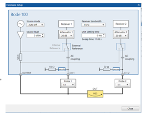
My customer has an application in the telecommunication service and bought a quantity of TLV9064. They need to do measurements for output impedance in an open loop. They did some measurements for it but can not do a measurement from TI example where they put a coil between output and IN- and a capacitor between IN+ to GND because it needs a coil of at least 10H and a capacitor 1F or more.

Any recommendation you can provide on how to do measurements for output impedance in an open loop?

Regards,

Renan

  • Hi Renan,

    I would run the OPAmp at a very high gain and do the measurement closed-loop to guarantee that the OPAmp is working at a proper DC operating point. I would take a simple sine wave voltage generator and a resistor between the generator output and the OPAmp output to generate a suited measuring current in the 100µA range and would inject this current into the output of OPAmp and measure the output voltage of OPAmp (voltage drop across the output impedance). This yields the output impedance for this set of measuring parameters. Then I would correct the output impedance by the help of the ratio between open-loop gain and closed-loop gain for this measuring frequency.

    Kai

  • Hello Kai,

    Please see the response from my customer:

    So I will put my negative feedback on inverting input and non inverting input to be at ground.can you give me an example for values of resistors from negative feedback from close loop on inverting input,for example. I will mention that I have a vector analyser to see the impedance. can I do that with it without signal generator on output,I think it has more precision. After what kind of formula I need to apply here to find the impedance from open loop?

    Regards,

    Renan

  • Hi Renan, 

    Kai's recommended test method works well for testing zo(open loop output impedance). 

    Ian Williams wrote a detailed blog on testing/simulating op-amp output impedance linked here: Test bench for op amps, Part 1: Output impedance

    The equations in the EDN can be used to calculate zo from a closed loop test.

    Is there a reason the customer wishes to test Zo themselves?

    Best, 

    Jacob

  • Hello Jacob and Kai,

    Please see response from my customer:

    Hi,it is because I have a sensitive application to design and I need to do measurements for Z out in open loop for different frequency.For that I asked you if you know practical methods for it.For this kind of masurament I will use a vector analyser witch has a better precision.with your methode I can not apply it because I don't have a big inductance of 1H or a capacitor of 1 F to apply this kind of methode to do masurament for Z output in open loop.

    Thanks in advance.

    Regards,

    Renan

  • Hi Renan, 


    Thanks for sharing the response with the customer. 

    The vector analyzer would work well for testing this. We use a Bode100 in my group to calculate Zo from gain/phase of AOL. See below for test configuration:

    We close the loop of the amplifier, and back calculate to get AOL being that we know the gain of the test circuit. You can then use the gain/phase of AOL to get to zo with a bit of excel wizardry. 

    Here are additional resources regarding impedance measurement from Omicron-Lab: https://www.omicron-lab.com/fileadmin/assets/Bode_100/ApplicationNotes/Impedance_Measurement_methods_using_the_Bode_100/2020-10-21_Bode_Appnote_Impedance_Measurements_V1_0.pdf

    Alternatively, you can use AOL and measure Zout( closed loop output impedance) to calculate Zo. This was the measurement method used in the Ian Williams article.


    1F caps and 1H inductors are easy to find in SPICE, not so much in real world testing. Slight smile 


    Give the zo measurement methods a try, and let me know if you have any questions. I looked at the some of our past test data for TLV9064, and all devices looked very similar to the datasheet plot for open loop output impedance. 

    Best,

    Jacob