Other Parts Discussed in Thread: ADS5407, LMH6554, THS4541
Hi,
Preface :
My application requires the input signal from a optical sensor which is in range of 0V to +/-1.8V to be driven to an ADC
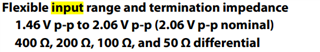
There are two signals one is in range of 0 to +2V and other 0 to -2V
The signals are in range of DC-250MHz
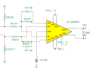
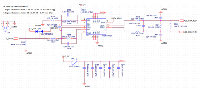
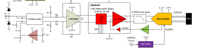
I have selected LMH5401 as my FDA before ADC(I wish to adopt TIDA-00826 reference design | TI.com )
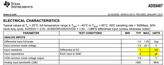
I have selected ADS5407 as my ADC
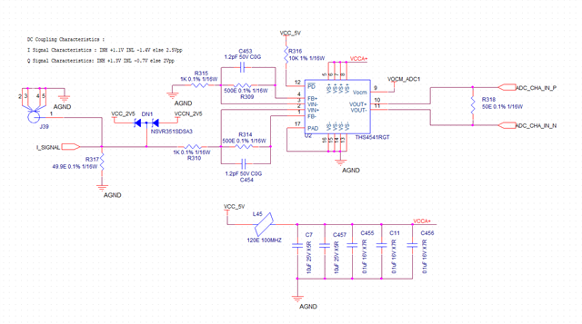
I wish to use the ADC for Both AC and DC coupling so i have given the option in my simulation for both and also given option of attenuation based on requriement.
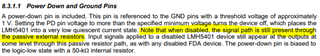
Below is my SCH
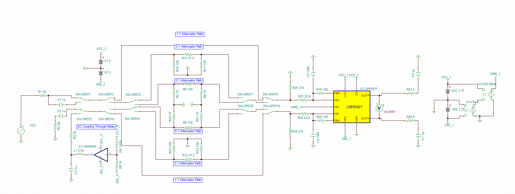
Attached also the TINA-Simulation-File
Kindly hlep me in understanding below
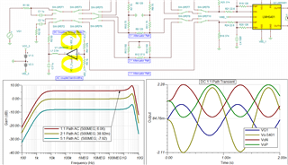
1. How to condition the Signal which is of below nature using the above circuitry to take to ADC

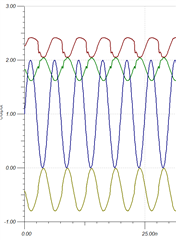
You can clearly see that my signal will have a DC shift in both channels, i wish to retain the DC shift because its a important parameter to measure, at the same time i also required to measure the AC variation in signal
At maximum the signal in Green Channel can touch +2V and Yellow Channel -2V
As taking this large swing to ADC is really tricky to me, high speed ADC i have seen will have swing of 2Vpp only
how to condition the signal to the ADC input
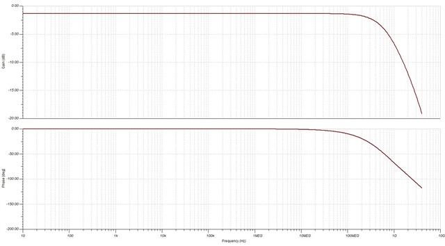
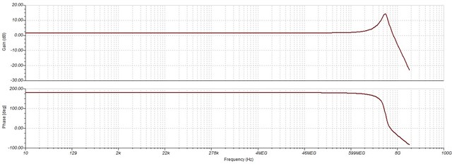
2. Why the simulation shows the plot of ADC gain negative that is less than 0dB ? am i doing wrong anywhere ? the fall 3dB/dec starts at 100Meg only why so ? i wish to operate the FDA up to 500Mhz with 1V/V Gain.