This thread has been locked.

If you have a related question, please click the "Ask a related question" button in the top right corner. The newly created question will be automatically linked to this question.

TLV333: Amplifiers forum

Part Number: TLV333
Other Parts Discussed in Thread: TLV3202

Hi,

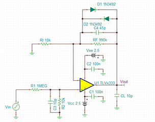
I am using the TLV333 in my circuit, please see picture:

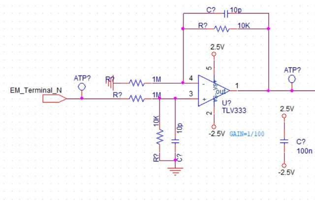
The EM_Terminal_N signal can change from -150V to +150V

I need to detect when this signal is above 0.1V or below -0.1V

From this circuit you can see that at 150V the OpAmp V+ terminal is 1.48V (ok for the OpAmp)

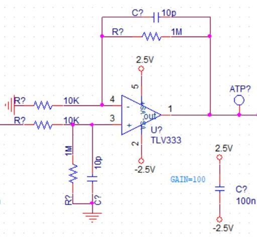
if the signal is 0.1V the output of the OpAmp is 1mV. After this OpAmp i use one more TLV333 OpAmp with gain of 100 (see picture below) to amplify the 1mV back to 0.1V, than it enters to comparators that detects the 0.1V:

My questions are:

1. Is it ok that the output of the first OpAmp will be 1mV and than i amplify it to 0.1V? the ripple and noise on the 1mV will be much lower from 1mV?

2. If I use just 1 OpAmp with GAIN of 1 instead of 2 opamps, than it will be ok for the OpAmp at +-150V because the resistor at V+ is 1Meg and the current to V+ is small? this is ok with the stress? The supply of the Opamps are LDOs, the current can flow back to the LDO from the +150V through the OpAmp?

Thank you

  • Hi Maor,

    is the only purpose of your circuit to detect this 0.1V / -0.1V threshold?

    Kai

  • Hi Kai,

    The purpose of the circuit is to detect when the EM_TERMINAL_N voltage reaches +-0.1V and +-5v and +-1V.

    In the start I had several comparators connected to this signal, but the voltage of the EM_TERMINAL_N can reach to +-150V so I did 2 opamps in series with 1/100 gain and 100 gain that will let me same voltage as the EM_TERMINAL_N without damage the comparators after the opamps.

    The total resistance between EM_TERMINAL_N and to ground needs to be minimum 1Meg ohm.

    Thanks

  • Hi Maor,

    Can't you just put the resistor divider in front of a comparator?  There are higher voltage comparators that allow for a wider voltage range, and you could add a clamp at the input, then you would not need to divide down by 100 and the detectable signal would be larger.  If you like we can forward to the comparator team to get their feedback.

    Assuming you want to go ahead with the amplifier - yes this circuit will generally work without problems. But, why use 2 amps. when you can use 1:

    The transient response can be seen below.

    This circuit has the 1/100 division, which is then gained back up by a non-inverting gain of 100.   The feedback capacitor was set to match the bandwidth of the loop gain of the amplifier (around 3.5 kHz).  The diodes are necessary to keep the amplifier from hitting the rails; without the diodes, when the amplifier output gets close to the supply voltage, it will no longer operate linearly; this leads to a longer settling time and is generally not recommended.  They will keep the output from giving an accurate result for 0.5 V input, though.  If settling time is not critical, you can allow the amplifier output to go to the rail but be aware that there are performance tradeoffs that need to be evaluated.

    Note you cannot get to +/- 5 V even when the diodes are removed; the output can only go to 100 mV from the supply voltage (+/- 2.5 V - 100 mV = +/- 2.4 V).  In order to detect +/- 5 V, you either need to use a higher voltage amp. and increase the supply voltage or use a lower gain.

    Let me know if you have any questions about the circuit above or if you want to check with the comparator team.

    Best Regards,
    Mike

  • Hi Maor,

    you could do it directly with a comparator as shown below. In this example the TLV3202 is used:

    maor_tlv3201.TSC

    Kai