This thread has been locked.

If you have a related question, please click the "Ask a related question" button in the top right corner. The newly created question will be automatically linked to this question.

LM258: LM258 VI pins shorted to GND

Part Number: LM258

Dear TI Team,

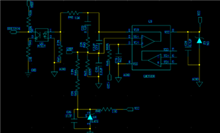
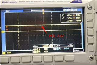
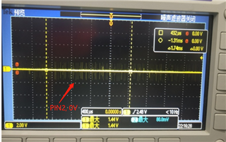
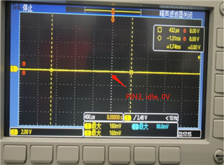
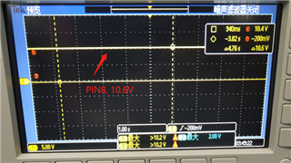
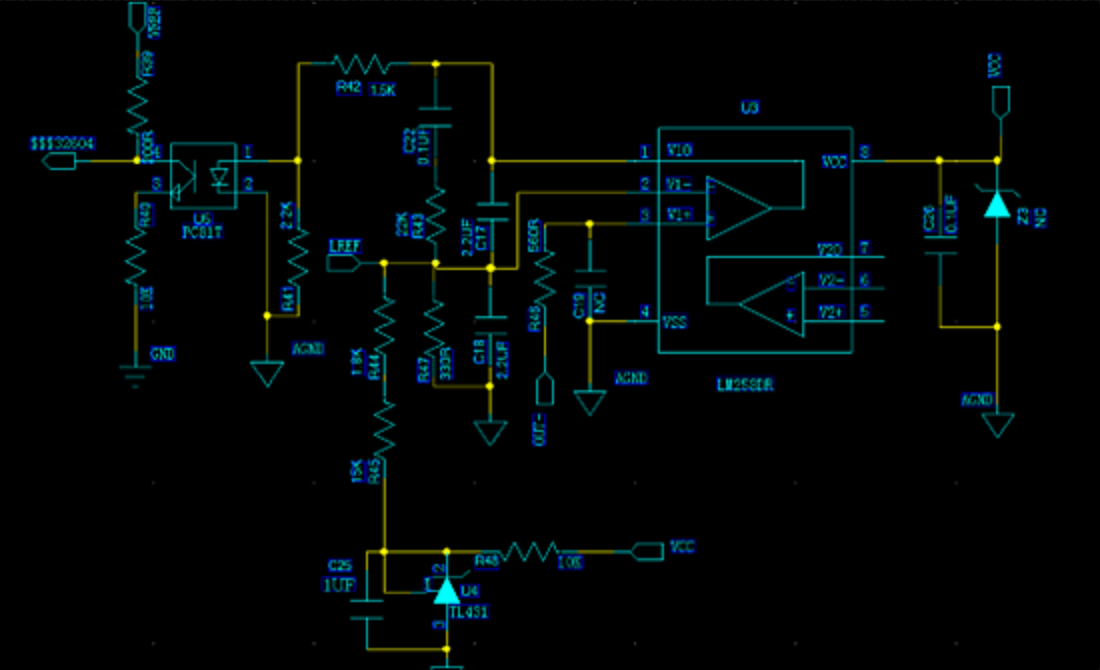
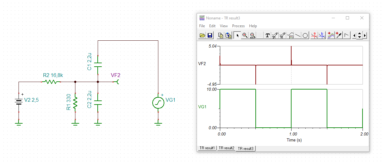
my customers used LM258 as a comparator in a product to compare the non-inverting input signal OUT- with the inverting input reference voltage LREF(The supply voltage on VCC is 10.6V). The product has shipped 260,000 units in batches. Recently, 28pcs failed products appeared. The specific problem was that PIN2 and PIN3 of LM258 were shorted to GND. The customer confirmed the problem by removing the chip and measure the impedance. Below is the schematic diagram and signals waveform. Please help to check whether there are design problems in the schematic. By the way, have you dealt with similar failure cases? Can you provide solutions or assist in failure analysis? Thanks!


  • Hey Rogers,

    Typically the cause for shorts to ground on the input is EOS or ESD. Does LREF go to a connector or go off board somewhere? That looks like the most likely path for EOS/ESD.

    Additionally, we do not recommend to leave the op amp floating. If you are not using the other op amp it is recommended to be connected as a buffer and with the input tied to a potential within the common mode voltage range. LM258 CMVR includes ground, so we recommend connecting it to ground through a 10k resistor to avoid ground bounce EOS.

    We have not seen an issue with the LM258

  • Hi Jerry,

    Thanks for your reply. About EOS/ESD problem, can TI help the customer analyze the failed IC for confirmation? Thanks!

  • Hi Rogers,

    this is no normal comparator circuit. R43, C17 and C22 are usually not seen in a true comparator circuit:

    Take care, C17 is killing the LM258! See what happens when the output of LM258 toggles low:

    rogers_lm258.TSC

    The -input of LM258 becomes negative and C17 has stored enough energy to destroy the input stage of LM258.

    Remove R43, C17 and C22 or at least add a current limiting resistor directly at the -input of LM258 as already mentioned by Jerry.

    Also increase the current limiting resistor R45.

    Kai

  • Rogers,

    The first step in analysis that TI would provide would be a curve trace to confirm presence of EOS damage, and the customer can much more quickly perform this check. This would simply confirm EOS damage.

    The first step in the return process is verifying the application is correct. Since the application has already been shown to be susceptible to EOS, the next action is to correct the application.

    Best,
    Jerry