This thread has been locked.

If you have a related question, please click the "Ask a related question" button in the top right corner. The newly created question will be automatically linked to this question.

OPA3S2859-EP: OPA3S2859-EP

Part Number: OPA3S2859-EP
Other Parts Discussed in Thread: OPA3S2859, TINA-TI

Hi,

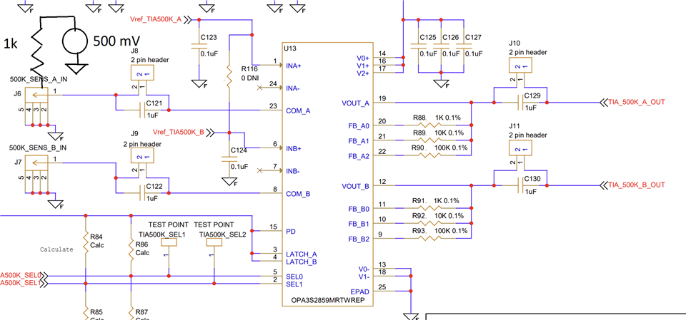
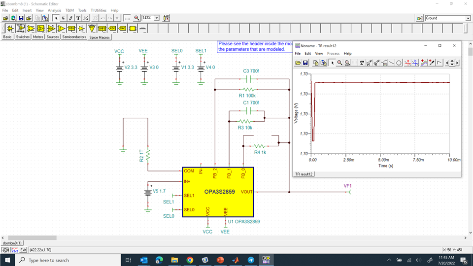
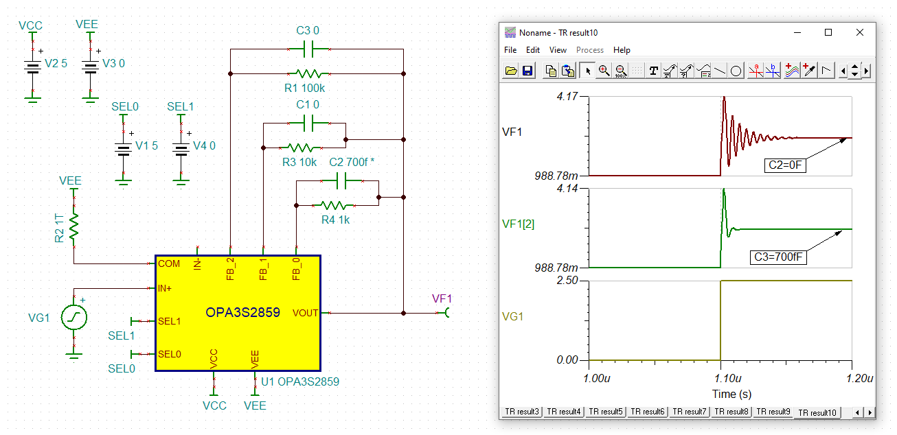
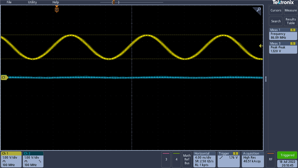
I have built the board according ref design. 10k, 100k branches work as expected but 1k branch oscillates at 80 MHz. 

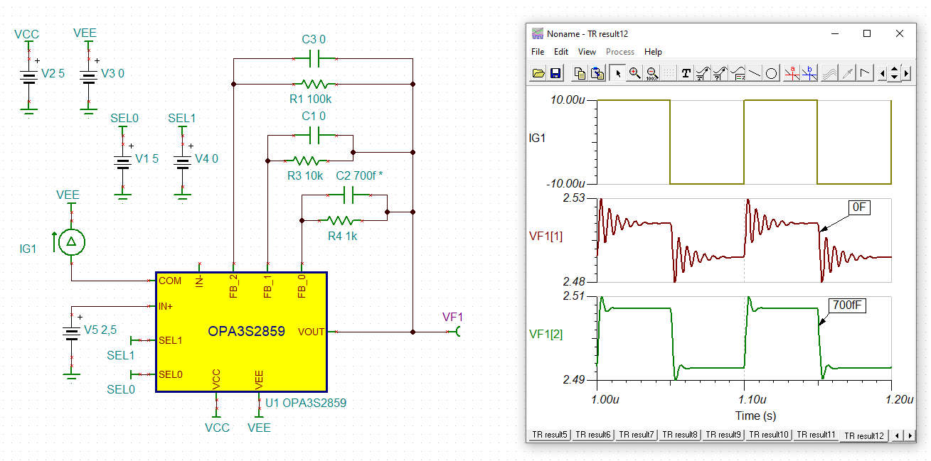
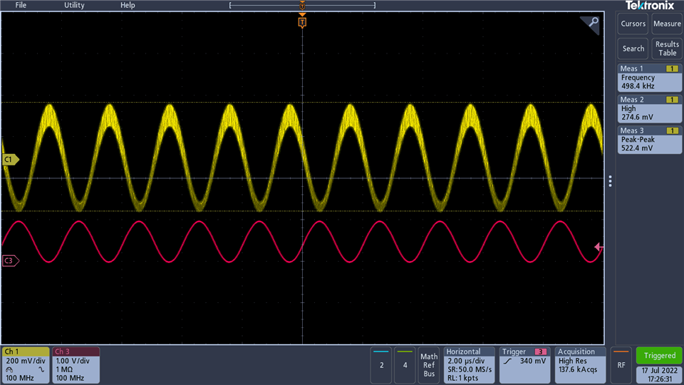
If I input 500 kHz current I have this signal

thanks vadim

  • Hi Vadim,

    which "reference design" do you refer? Or do you mean the "test circuit" shown in figure 9-1 of datasheet? Please show a schematic, if your circuit differs from this circuit.

    Keep in mind that the circuit will only work properly (stably!), if your photodetector has the same detector capacitance as given in the test circuit. With a differing detector capacitance the phase lead compensation provided by the phase lead capacitors in the feedback paths may have to be adjusted.

    Also keep in mind that you must not connect the scope probe directly to any pin of the OPAmp. This may cause instability and result in oscillation. Always use a suited isolation resistor. The test circuit has a 169R and 71R5 resistor to provide a 50R series termination impedance to match a 50R cable. So connect a 50R cable at the connection point of these two resistors. The 50R resistor at the right of these two resistors is meant as 50R input impedance of scope. When connecting a 50R in this way, no isolation resistor is necessary.

    And tell more about your photodetector. How far is it away from the OPAmp? Is any cabling involved?

    Kai

  • Hi Kai,

    thanks for your support! I actually built two boards of the same schematics. The first one that used 0806 parts does not have oscillations, the second one with 0402 has. We use the chip as TIAs and the schematics is here. The oscillations happen even when nothing is connected. If the oscillations related to layout i still have to find a fix. In your ref design 

    https://www.ti.com/lit/ug/sbou263/sbou263.pdf?ts=1658187302915

     there were provisions for caps. Are their  purpose to decrease the gain for higher frequencies? 

    thanks vadim

  • Hi Vadim,

    it's not wise to operate the OPA3S2859 without any phase lead compensation. This can result in instability and oscillation.

    Why not running a TINA-TI simulation?

    vadim_opa3s2859.TSC

    C2 is stepped from 0pF to 0.7pF.

    Kai

  • Hi Kai,

    Tina does not show oscillations being built up with current transient analysis settings

    Is there a way to set up a max time step in simulations, so it can build up oscillations. now the part oscillates like an oscillator with no connections at the input

    thanks vadim

  • Hello Vadim,

      Analysis parameters in Tina-TI are located under Analysis tab --> Set Analysis Parameters (or ctrl + alt + p). 

      Are the boards layout identical? If so, then you mentioned that the board with the 806 parts does not have oscillations, but the second board with 0402 does exhibit oscillations, then this does seem to point to the need for feedback capacitance. Would you be able to solder around 0.7pF right on top of the component, if you do not have the pads? 

    Thank you,

    Sima 

  • Hi Vadim,

    usually you need a stimulus in the simulation to show instability. A suited stimulus contains all frequencies from the lowest to the highest to be able to invite the instability to respond. So you need a broadband signal for the stimulus, for instance a sharp edge. That's why I used a square wave signal in my first simulation. But you can provide the stimulus elsewhere, for instance at the "IN+" input of OPA3S2859, see below. Sometimes even applying the stimulus on the supply voltage pin can work.

    The long ringing of the brown curve is a clear indication for instability of the circuit. In a stable circuit you never want to see such a long ringing.

    And to force sustained oscillation adding some load capacitance can do the trick:

    Kai

  • Hi Sima and Kai,

    I will try caps. In spice, noise of calculations with small time step can help build oscillation in simulation, but your approach will work too.

    thanks for your support!

    vadim