This thread has been locked.

If you have a related question, please click the "Ask a related question" button in the top right corner. The newly created question will be automatically linked to this question.

OPA376: OPA376 Differential amplifier problem

Part Number: OPA376

Hello support team,

I am working on a differential circuit with the OPA376AID which interfaces between a current sensor and an ADC and I do not have the expected behavior of the differential circuit.

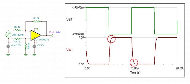
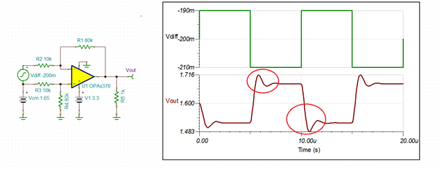
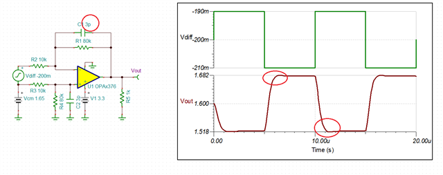
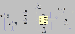
Here is the circuit:
R1=R2=R=10K
R3=R4=R'=80K
Vout=(V2-V1)(R'/R)

Input:
V1 = 1.65V
V2 = 1.65V

Theoretically I should have Vout ≈ 0 V, which is confirmed by the simulation on LTspice.


This is what I'm measuring :

Vout = V2 = 1.65 V, I have the behavior of a voltage follower, Indeed I have always Vout = V2 ...

Do you have an explanation ?

Please correct them if there is a mistake.

Best regards,

Constant

  • Morning Constant,

    So you seem to be comparing a sim output to bench measurement? Yes, in theory the output should be 0V. Keep in mind the part will have trouble going exactly to 0V physically (look at output swing spec). Try injecting a 0.1V into the bottom of R4 to raise the output off ground.. It is possibly your physical circuit is missing a connection. 

    Can you attach your .asc file, 

  • Hi Constant,

    take care, the OPA376 comes in three different packages with three different pin configurations.

    Kai

  • In short, what package do you use?

  • Hello again,


    I solve my problem, the circuit works correctly now I just changed the resistors R=1K and R'= 8K (initially R=10K and R'=80K)

    Thanks for your answers

    Regards

    Constant Maury

  • Constant,

    What this means is that the circuit was unstable with 10k input resistor. Since the R2 resistor interacts with the input capacitance (Cin=6.5pF+13pF) forming a zero in the G(f)=Vout/Vin transfer function, using R2=1kohm results in fz=1/(2Pi*R2*Cin) = 1/(6.28*1000*19.5pF) = 8.16MHz - thus, this is well above the effective bandwidth of OPA376 in G=-8 (BW=GBW/Gain=5.5MHz/8=~700kHz) and therefore doesn't affect stability of the configuration - see below.

    However, using R2=10kohm results in fz=1/(2Pi*R2*Cin) = 1/(6.28*10,000*19.5pF) = 816kHz - thus, this is very close to the OPA376 effective bandwidth of 700kHz, which results in marginal stability - see below.  This means that your original circuit most likely was oscillating with average value of 1.65V.

    However, there is a simple solution to this problem by canceling the zero by adding 3pF feedback capacitor so R2*Cin=R1*C1.  This stabilizes the circuit without the need to lower the values of the resistors used - see below.

  • Hello Marek,

    Thank you very much for your explanations.

    Regards

  • No problem. Good luck!