This thread has been locked.

If you have a related question, please click the "Ask a related question" button in the top right corner. The newly created question will be automatically linked to this question.

OPA2810: Bulk capacitance Guidance for Sharing Amongst Amplifiers

Part Number: OPA2810

Hello,

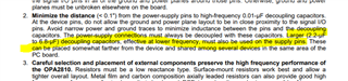
In the OPA2810 it recommends using a larger capacitor for the power pins and mentioned that it can be shared among several devices.  Do we have any more details on constraints for sharing?

In our design we have a large copper pour for this power rail  and are using numerous OPA2810s.  The OPA2810s are in the same area (roughly 3x3 inches).  We were interested if TI had more guidance on how this capacitance could be shared.  

  • The supply capacitors are there is to shunt out any supply trace inductance that would otherwise present a high impedance at high frequency. Source inductance is a problem when the amplifier tries to drive a high frequency load current. Since even capacitors themselves have a self-inductance at high frequencies, usually a smaller, lower value capacitor is also recommended next to each individual device if maximum frequency output current is expected.

    You might limit the slew rate if all of the amplifiers tried to drive a large, fast step response at once, and if you are trying to achieve very high small signal unity gain bandwidth from each device, you probably still want a lower value capacitor by each device even if they share a common ~1uF main supply decoupling capacitor. If this were a higher bandwidth device, you would also need these for loop stability alone, but the OPA2810 is a lower bandwidth, large signal device that should be more intrinsically stable.

  • Hi Jason,

    paralleling of uneven decoupling caps dates from an area when large capacitances came only in large packages. And because only the small capacitances in their small packages showed sufficiently low series inductance, you needed to combine both to cover the whole frequency range with the supply voltage decoupling, the smaller capacitance for the higher frequencies and the bigger capacitance for the lower frequencies.

    This has fundamentally changed today. The modern "ceramic high caps" provide huge capacitances in ultra tiny SMD packages and offer both, very high capacitance in combination with ultra low series inductance. So the preferred way to decouple a HF-OPAmp today is to use only one 2.2µF...10µF / X7R cap in 0805 or even 0603 package and to mount it directly (!) at the supply voltage pins of OPAmp, while the ground terminal connects to the solid ground plane.

    Paralleling of uneven caps is critical because when the ESR of both caps is very small, nasty resonances between the two caps can occur resulting in a high impedance of the parallel combination at the resonance frequency, where the decoupling caps have lost all their decoupling abilities. For this frequency the decoupling caps appear to be no longer present, as if you have omitted them at all. Have a guess at what frequency the HF-OPAmp will oscillate...

    Happily the large capacitances of the past in their large packages have usually had enough ESR to dampen this parallel resonance. Think of tantal caps, e.g., with their finite ESR.

    Ceramic high caps, on the other hand, behave totally different. Their ESR is ultra-low and when paralleling two uneven ceramic caps (10nF + 2.2µF, e.g.) a heavy resonance can occur. This resonance can be so heavy that sometimes even an additional resistor of about 0.47...2R has to be mounted in series to the larger cap. The preferred remedy is to use either only one decouping cap (see above) or to parallel two identical ceramic high caps.

    Another problem is that supply voltage connections between OPAmps can look inductive and can cause unwanted resonances with the decoupling caps. This is the more critical the faster the OPAmps are and the lower the ESR of decoupling caps is. Here again the legacy parallel circuit of small capacitance and large capacitance behaves totally different compared to the modern ceramic high caps. The large capacitance has enough ESR to dampen also these resonances. At the same time the large capacitance shifts the resonance frequency according to the Thomson formula to lower frequencies where less ESR is needed to dampen the resonance, according to R > SQRT(2L/C).

    When using ceramic high caps, on the other hand, a good remedy is to use Pi-filters at each supply voltage pin of HF-OPAmp. In combination with the modern state-of-the-art ferrite beads available today, Pi-filters very effectively isolate the OPAmps from each other and instability caused by resonances of the common supply voltage line is no longer probable. Even separate power planes may no longer be necessary in many applications. When I have to use several HF-OPAmps on the same board I always use Pi-filters in the supply voltage lines and I have never regretted it. The no longer used power planes I use as additional ground planes.

    If you don't want to use Pi-filters but stay with your current design, I would recommend to mount a 10nF cap directly (!) at each supply voltage pin and to mount an additional 2.2µF cap with sufficient ESR close to each 10nF cap. In contradiction to the datasheet which says that "the larger cap can be placed somewhat farther from the device", I would mount it closest to the 10nF cap. It's no good idea to have any unwanted inductance between paralleled decoupling caps (L1 steps in the simulation from 0nH to 5nH, which equals about a 5cm long copper track):

    jason_opa2810.TSC

    The green impedance peak at 17MHz exactly is what you don't want to have in an HF-OPAmp circuit. The aim usually is to provide a "flat" impedance curve of under 1R at the higher frequencies, up to about twice the bandwidth of OPAmp which is 200MHz here.

    Kai