This thread has been locked.

If you have a related question, please click the "Ask a related question" button in the top right corner. The newly created question will be automatically linked to this question.

OPA388: Phase Current Abnormal Waveform

Part Number: OPA388
Other Parts Discussed in Thread: UCC27211,

Hi all,

I have custom design BLDC driver board with OPA388 amplifier and UCC27211 gate driver IC. I attached the 3 phase current measurement screens. I couldn't measure the third phase as I expected. Do you have any suggestion ? Schematic also attached.


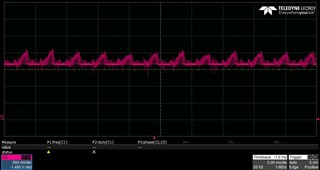
Normal U and V phases
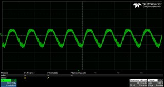
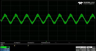
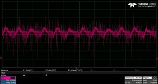


Abnormal W phase


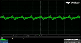
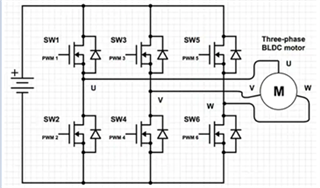
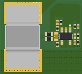
Gate driver schematic
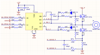
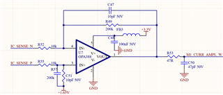
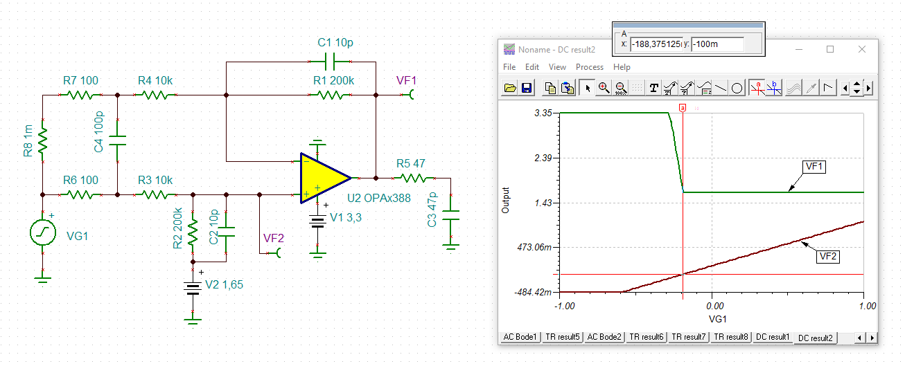

Current sense:

  • Hi Alikaan,

    are the scope plots showing the outputs of OPA388?

    Can you show scope plots of the inputs signals (across R19, e.g.) as well?

    Kai

  • Hello,

    Please check the attached.

    This one abnormal phase's op amp output.


    These are normal phases.

  • Also I changed the shunt value to 10 milliohm for low current measurement.

  • Hi Alikaan,

    I assumed that your BLDC motor configuration is similar to the block diagram below. Could you add phase U and V in current (green plot) and compare it with the current in Phase W? The phase W should be the returned current of U + V. 

    The abnormal voltage drive looks strange. It seems that it is missing bottom part of the drive.Could you see if any components are damaged on that phase?

    Best,

    Raymond 

  • Hi Alikaan,

    Noticed: R57, C51 silks are reversed in your Gerber!

    The sawtooth current phase W (green) is not uncommon sensorless SVPWM. Sometimes switching V&W so triangle wave takes center phase gets better results, may change motor rotation direction. Also notice fair amount of THD in all current probe wave forms, what PWM frequency? Clarke current formula (Sensorless FOC) can be changed to handle uneven phase currents, may help to clear some THD. 

    Regards,

  • Hi Alikaan,

    because you have set a very high gain in the differential amplifier, the common mode voltage is only 1.65V / 21 = 79mV. So even the least noise betwen the ground of shunt and the ground of OPAmp will make the common mode input voltage exceed the allowed range:

    alikaan_opa388.TSC

    There are several remedies:

    1. Decrease the ground noise by moving the differential amplifiers closer to the shunt. Additionally minimize any ground noise between the involved grounds by clever ground routing of motor current.

    2. Decrease the gain or even heaviliy decrease the gain of differential amplifier. This gives you more headroom for suppressing of common mode noise (ground noise). And it helps to better handle the far reaching harmonics of signal.

    Also, do not connect the lower terminal of C51 to the 1.65V pseudoground but connect it to signal ground of OPAmp. The pseudoground generation might have problems to absorb the HF common mode noise running through C51.

    Kai

  • Hi Raymond,

    We removed all the current sense amplifier circuit components and re-soldered with unused components. Nothing changed. Also BLDC motor configuration is correct. If I can measure the phase currents correctly, as you said, W should be equal to U+V but now we have abnormal phase current.

  • Hello Kai,

    Please check the layout of current sense amplifier and shunt resistor. They are very close to each other. 


    We will decrease gain and I'll post the newest current measurement graps.

    Thanks.

  • Hi Alikaan,

    keep in mind that you have three shunts with three ground terminals. And you have the three signal grounds of OPA388. All these six grounds must have the same potential. This is impossible in reality when big currents are running. So there will common mode noise develop between the grounds and at least one of the three differential amplifiers in your apllication is not able to suppress it.

    Can you show a photo of the layout which shows all three shunts together with their OPA388?

    One remedy to minimize the common mode noise (voltage drops between the ground terminals) is to use a ground star point (in the form of a local ground plane), where all the three ground terminals of shunts are connected to. Connect the signal grounds of the three OPA388 also to this ground star point (local ground plane). Have no ground connection elsewhere.

    Use the ground star point (local ground plane) method in combination with a decrease of gain of differential amplifiers to allow the OPA388 a higher common mode rejection.

    Another remedy is to use a current sense amplifier or even an isolation amplifier which you can mount directly at the shunt. These amplifiers may be necessary when the common mode noise (voltage drops between the ground terminals) is so high that it cannot be suppressed by the simple differential amplifier. Current sense amplifiers and isolation amplifiers show a very high common mode rejection and show much better performance compared to the simple differential amplifier.

    Current sense amplifiers can be found here:

    https://www.ti.com/amplifier-circuit/current-sense/analog-output/products.html

    Isolation amplifiers can be found here:

    https://www.ti.com/isolation/isolated-amplifiers/products.html

    Kai

  • Hi Alikaan,

    Agreed with Kai's recommendation. You need to resolve the current sensing issues, since the current sensing is used to generate the PWM feedback signals. Please also compare the current sensing vs. the current probe measurements. This will indicate that if the current sensing is making a good measurement.  

    Enclosed is a video about the current sensing methods. Since your supply voltage is not high at 28Vdc, you may also consider high side current sensing method. The high side current sensing method will have less noisier than the low side current sensing. The best method is inline current sensing for motor application, but it will introduce a lot more circuit in the design. 

    https://www.youtube.com/watch?v=o_DY9gQKjUI

    Best,

    Raymond