This thread has been locked.

If you have a related question, please click the "Ask a related question" button in the top right corner. The newly created question will be automatically linked to this question.

LMH6401: Daisy chain question

Part Number: LMH6401
Other Parts Discussed in Thread: SN74CBTLV3251

Hi,

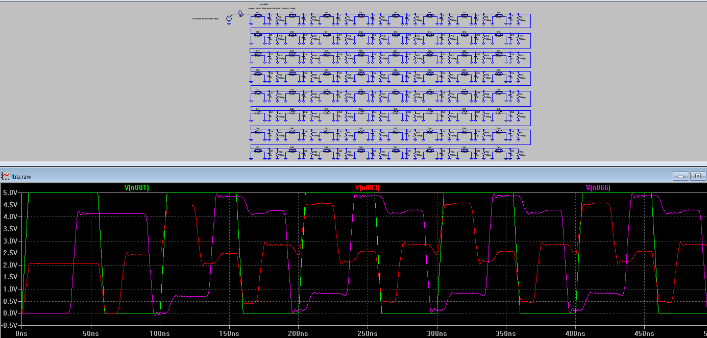
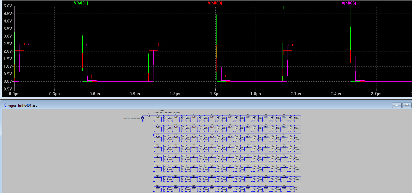
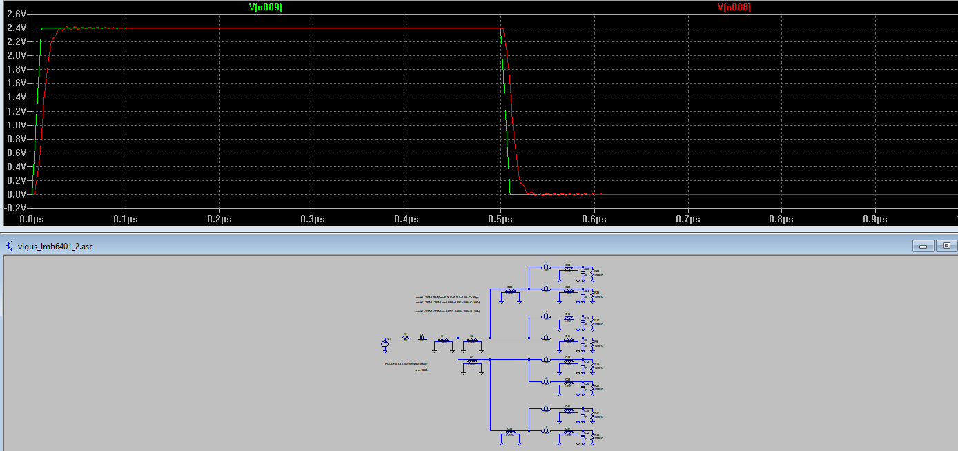
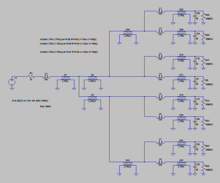
I would like to daisy chain 64 of thes parts on the same SPI bus direct tie the SCLK and SDI pin together with separate independent CS and SDO. Is it possible? Can you tell me the current required for the SCLK and SDI?

Thanks.

VD

  • Hello VD,

    I will check with my team on the feasibility of this design.  In the future, you may edit your posts to add additional questions, or use the 'ask a related question' button instead of posting two separate questions:

    https://e2e.ti.com/support/amplifiers-group/amplifiers/f/amplifiers-forum/1133375/lmh6401-daisy-chain

    I will be responding to the entirety of your question here in this active thread.

    Best,

    Alec

  • Hi Vigus,

    I think the capacitive loading of the daisy chain is the real problem here. Keep in mind that in opposition to the I2C bus the SPI is a high speed bus running up to 50MHz. This requires a SCLK driver in the master providing steep edges. This works well when only two or three LMH6401 are connected to the master and the distance of SCLK line is only a few centimeters. But when driving a longer daisy chain transmission line effects like echoing and ringing will be seen.

    A longer transmission line for a point to point transmission (one master and only one slave) is not the problem, because you can easily introduce series termination at the driver. But when daisy chaining the numerous input capacitances of the many slaves will come into play. And this will not work even not with series termination.

    In the following simulation you can see the behaviour of a daisy chain containing 64 slaves, each with 3pF input capacitance and all slaves distanced by 3cm long 0.3mm wide copper tracks being routed over a 140µm distanced solid ground plane. The 3cm long copper tracks equal a transmission line impedance of about 129 Ohm and the whole daisy chain is series terminated by the help of a 129R resistor at the master:

    The green curve is the 10MHz SCLK signal of the master with a rise and fall time of 5ns. The red curve is the signal received by the first slave and the violet curve is the signal at the last master. You can clearly see that the echoing is totally ruining the SCLK signal.

    Increasing the rise and fall times of signals of master to 100...200ns and decreasing the clock rate way below 1MHz can help to avoid the nasty echoing. But the slaves must be able to accept the decreased rise and fall times at their inputs.

    vigus_lmh6401.zip

    Kai

  • Hi Kai and Alec,

    I receive a similar inquiry as this thread. 
    What solution can you reccomend? Will it help if a two stage fanout using sn74cbtlv3251 (or similar), first 1 to 8 fanouts and then another stage. Will this help?
    Regards,
    Marvin
  • Hello Marvin,

    I can spend a bit of time looking into the specifics of fanouts and how to properly handle and terminate SPI communication lines.  I am not particularly familiar with the topic, but I will investigate.  From what I can tell, Kai's response appears to cover some pros & cons of operating this many devices on an SPI bus, but I digress I need more time to formulate an opinion from my experience.

    I would be happy to keep you updated and work with you on a solution.

    Best,

    Alec

  • Hi Marvin,

    first, one would need to know how the SPI bus is actually physically looking like. What are the actual distances? How are the bus lines split up? So a layout would be very useful.

    The maximum distance of bus lines from the master to any slave determines the maximum clock rate because of the unavoidable signal delay of transmission lines.

    Then, it can be tried to terminate the transmission lines (bus lines) at both ends. This would allow to have many slaves being connected to the same transmission line, way more slaves than in a point-to-point transmission. But becasue of the signal dampening this would eventually require special bus line drivers / receivers at the inputs and the outputs:

    Kai

  • Hi Alec and Kai,

    Thank you for helping. 

    Looking forward to your response.

    Regards,

    Marvin

  • Hello Marvin,

    As Kai mentioned, it would be easier to assist with your design questions if we had a better understanding of your physical board setup/layout.  Are there any parameters or details you can put here on the forum regarding your layout.

    Proper termination and the issue of signal degradation are important here; I am checking with my team on our prior exposure to questions about this kind of design to see if we have any tips or ideas.

    Best,

    Alec

  • Hi Alec and Kai,

    The layout is not yet done but I attached the sample layout and more information from the customer

    images.zip

    In image(4) and Image(5)b is the carrier board, connecting the SCLK and SDI from one connector to 8 connectors. 
    Currently, the carrier board size is about 100mmx250mm. So the trace length on the trunk of the bus on carrier board is about 300mm, and each branch is about 10mm. There is no terminator on this bus design yet, what kind of terminator should they add?, a resistor to ground matching with the characteristics impedance of the bus? The bus is not on an impedance controlled layer (which is used for the RF trace). 
    Each of the 8 connectors will be 4 RF channels, and each will have 1-2 SPI clients. In image(3), the SCK pin is highlighted from the connector to the chip..
    The width for the daughter is about 55mm, and the length vary for different design between 50mm-120mm. So the SCK and SDI bus share one bus trace to the place where the part is and then fan out to each chip . 
    maybe the right question to ask is how to get 8x8=64 spi devices to work together. 
    What is the recommended approach for that?
    Regards,
    Marvin
  • Hi Marvin,

    you can have success when inserting Schmitt trigger receivers at the daughter boards. One for each line. This would isolate the bus lines from the capacitive loads of the four LMH6401 on each daughter board.

    The following simulation shows the situation with 129R transmission lines on the boards (0.3mm wide copper track routed over a 140µm distanced solid ground plane), a 2.4Vpp square wave of 1MHz with rise and fall times of 10ns and a simple 75R series termination. The bus lines are simulated by differently long transmission lines and the connectors by 15nH inductances:

    vigus_lmh6401_2.zip

    By keeping the series termination resistance smaller than the transmission line impedance ripple free edges can be generated. Of course, you have to experiment with the concrete value of series termination resistor to optimize the result.

    There are certain requirements which must be fullfilled for a stable performance:

    1. You cannot route the bus lines close to each other. Crosstalk will totally ruin the signal integrity. You MUST isolate the bus lines by sufficiently wide ground fills between the bus lines which you MUST connect to the underlaying solid ground plane by as many vias as possible (at least every 10mm or so).

    2. Additionally, you MUST route the bus lines over a solid ground plane. Only by following these two design rules crosstalk can be prevented and a predictable signal shape can be achieved.

    3. To stay well away with the rounded knee and the ripple of signal from the threshold level of Schmitt trigger receiver, the amplitide of square wave should be no more than twice the threshold level of Schmitt trigger receiver.

    4. It's important to drive the bus lines with a square wave not having too steep edges. Because of this the bus line driver shot not be too fast here. The slower the better. Run the simulation to see the impact of rise and fall times on the unwanted ringing. It mainly depends on the Schmitt trigger receiver how much ringing can be accepted.

    5. The clock rate of SPI bus should not be too fast. I would recommend to stay below 1MHz or so.

    A last hint: Keep in mind that using ground fills between the bus lines will change the transmission line impedance. This should be considered when running the simulations. In the above simulation I don't have assumed these ground fills.

    Kai