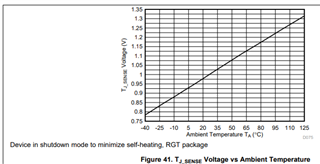
I'm looking for some guidance on how to interpret the TJ_SENSE specification for the THS3491. Since the test condition is to disable the part (Pd = 0V), the Ta is somewhat close to Tj, but what does the temperature value on parameter TJ_SENSE 25degC value actually mean? Also, if I look at the curves between MIN, TYP, MAX, at a specific voltage - say 1.1V, the temperature can vary almost 70 deg C, assuming the coefficient of 3.2mV/C. If this is really true, then how can I use the value to estimate the junction temperature? Figure 41 in the specification just seems to confuse me more. From my interpretation, I can't really use this voltage (TJ_SENSE) to estimate the junction temperature without a calibration of each part and probably on the TI EVM? I also tried plotting the curves with the knowledge that the test condition Ta varies from 22C to 32C, but it doesn't seem to help much. For now, I can assume the 1.06V is for a Tj of 25C and a coefficient of 3.2mV/C to calculate a junction temperature but will not rely on it.

-
Ask a related question
What is a related question?A related question is a question created from another question. When the related question is created, it will be automatically linked to the original question.