This thread has been locked.

If you have a related question, please click the "Ask a related question" button in the top right corner. The newly created question will be automatically linked to this question.

LM358: Voltage Amplifier LM358

Part Number: LM358
Other Parts Discussed in Thread: , LM324B

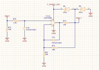
Hey, by providing a DAC input, I'm using the LM358 as a voltage amplifier to produce a 0-10 V signal. The image is included below.
V_Supply_Filter is a 24V
I want to ask if I can remove the SS34 diode. How do I add reverse polarity protection to the output.

  • Hey Dheeraj, 

    Could you share the expected signal (voltage range, frequency) out of DAC5? 

    All the best,
    Caro

  •  STM32F303VCT6 controller I am using to generate the DAC signal, and that is 12bit DAC. So the digital range is (0 to 4095). 

  • Hey Dheeraj, 

    Could you please specify the expected signal in analog? The voltage range and frequency? 
    I looked at the datasheet of the device you specified, is 0 to 3.6V a fair assumption? 

    All the best,
    Carolina

  • DAC: 0 to 3.3V after Opamp it will be 0-10V 

  • Hi Dheeraj,

    the OPAmp provides a gain of 4V/V. Because of that an input voltage of 3.3V would translate to an output voltage of 4 x 3.3V = 13.2V. Correct?

    Please explain why the "SS34" diodes are mounted from the output to the supply rails at all.

    And please explain what is connected to the "AVO_5" output.

    Kai

  • Sorry, the voltage reference is set to 2.5V, which is why the opamp gain is set to 4 for generating the 10V signal. AVO_5 is an analog output that will be connected to the  actuator. The SS34 diode is in place for the ESD protection because we are powering up the opamp directly from the 24V.

  • Hey Kai, any update on this. 

    Thanks

  • Hi Dheeraj,

    what are the two "SS34" protecting against? Inductive kickback from the actuator or is it only for ESD protection? Or is it for reverse polarity protection as you mentioned in your original post? How shall the SS34 protect against revrese polarity? Reverse polarity coming from where? The supply voltages? The input? The output? Why are you expecting reverse polarity? And why are you wanting to remove the "SS34", if they protect your circuit?

    Sorry, but I don't understand you. Can you please explain in detail what you are planning to do?

    Kai

  • Hey Kai, Sorry for not providing the clarity earlier. 

    Instead of reverse polarity protection, SS34 is installed for ESD protection. I need to get rid of these without altering the original signal data because SS34 is larger and I don't have room left on the board for them. I need assurance that the system will function normally if I remove SS34 for that reason.

  • Hey Dheeraj, 

    Is there a chance to switch over to LM358B? The LM358 does not have ESD protection structure but the B version does. Therefore the diodes would not be necessary. 

    All the best,
    Carolina 

  • Hey Caro Yes, I can switch to that.

    Currently, I am using a 4-channel LM324N and a 2-channel LM358D for the same operation. Should I also change something for the LM324N, or would that work fine without diodes?

  • Hey Dheeraj, 

    Correct, the LM324N does not have internal ESD protection, the LM324B offers internal ESD protection cells.Here is a snippet from the datasheet.  

    I recommend leveraging Design Guidelines for Devices with LM324/LM358 Cores (Rev. A) along with the respective datasheets when implementing your design changes. 

    All the best,
    Carolina

  • Hi Dheeraj,

    1. It's unusual to use the "SS34" which is a big 3A Schottky diode for ESD protection. The "BAT54S" may be better suited.

    2. The "LM358B" withstands 2kV HBM ESD. But when the customer can touch the output of "LM358B" the CE standards demand to withstand 8kV HBM ESD. Because of that, the add of an external ESD protection clamp at the output can make sense. The "BAT54S" is often used for this purpose.

    3. The "SS34" being a big 3A Schottky diode shows a huge junction capacitance of 200pF...1000pF (depending on the reverse voltage) which can make the OPAmp circuit instable.The developer of your circuit has used the "dual feedback method" which is often used when a big load capacitance has to be handled but the circuit is still instable. See the following phase stability analysis:

    brian_lm358b.TSC

    With the "BAT54S" offering a way smaller junction capacitance the phase margin is better and the circuit is stable:

    (The aim is to establish a phase margin of > 45°, better 60°. Then there are no stability issues.)

    But when you connect a cable to the output the additional cable capacitance will ruin the phase margin again. A 2m long cable with 200pF will give a phase margin of only 30°.

    Reducing your C53 can help to restore the phase margin again and even allow the connection of cables:

    4. There's a nice TI's training video series on stability, also discussing the dual feedback method:

    https://training.ti.com/node/1138805

    5. For best ESD protection move the BAT54S (but only the BAT54S) a bit away from the LM358B, best close to the connector where the signal leaves the board. Have a 100nF decoupling cap there for the 24V supply voltage and connect the upper BAT54 to this decoupling cap.The lower BAT54 connects to the ground terminal of this decoupling cap which sits in a solid ground plane. Connect from this ground point a 1...10nF Y-cap to the metall chassis. By this ESD is very effectively hindered from entering the whole board. The ground point of said decoupling cap, and the connector of course, should sit closest to the edge of board and the metall chassis.

    Use a solid ground plane for the circuit and have the decoupling cap of the LM358B closest to the supply voltage pins.

    Have all connectors sitting on one side of the board. This also hinders ESD from travelling over the whole board, from one connector to the other.

    Kai

  • Thanks, Kai for the brief reply. I will surely consider these guidelines.