Other Parts Discussed in Thread: OPA2188, OPA2197, OPA2192, OPA4196
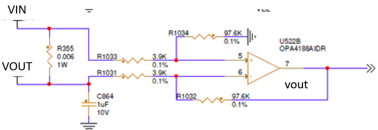
I'm using the OPA4188 to measure voltage drop across a .006 Ohm shunt resistor. My test setup is a programmable supply that I can vary from 0.6V to 5V which connects to 4 separate .006 Ohm shunt resistors all connected in parallel, the other side of the shunt resistors is connected to an electronic load that I vary from 1 to 17Amps. The circuit is using this QUAD op-amp to measure voltage across each shunt resistor with a nominal gain of my circuit setup to approx 25. Schematic just shows one of the 4 channels in the package but all 4 are configured the same way. V+ is biased with 15V and V- is biased with -3V.
My first test was to set a fixed current of 7Amps so expect roughly 1.75A of current through each shunt resistor. I then vary my shunt voltage source from 1 to 5V in 500mV increments. Measuring my actual Vdrops across the shunt resistor and getting the ratio of the op-amps output voltage to confirm I'm getting my gain of approx 25. This works well from 1 to 2V and then from 3.5V to 5V, but for some reason at my 2.5 and 3V points my gain increases to as high as 37.5. This is very consistent across 5 different prototypes I have.
| Vdrop on .006 Ohm shunt | op-amp output | Calc Gain | ||||||||||
| Shunt Source Voltage | CH-A | CH-B | CH-C | CH-D | CH-A | CH-B | CH-C | CH-D | CH-A | CH-B | CH-C | CH-D |
| 1 | 0.0115 | 0.0106 | 0.0106 | 0.0096 | 0.303 | 0.284 | 0.284 | 0.249 | 26.34783 | 26.79245 | 26.79245 | 25.9375 |
| 1.5 | 0.0115 | 0.0106 | 0.0106 | 0.0096 | 0.2956 | 0.2653 | 0.263 | 0.2422 | 25.70435 | 25.0283 | 24.81132 | 25.22917 |
| 2 | 0.0115 | 0.0106 | 0.0106 | 0.00965 | 0.2979 | 0.2672 | 0.2643 | 0.2426 | 25.90435 | 25.20755 | 24.93396 | 25.1399 |
| 2.5 | 0.01155 | 0.0106 | 0.0106 | 0.0096 | 0.338 | 0.398 | 0.355 | 0.275 | 29.26407 | 37.54717 | 33.49057 | 28.64583 |
| 3 | 0.01155 | 0.0106 | 0.0105 | 0.0097 | 0.311 | 0.349 | 0.337 | 0.245 | 26.92641 | 32.92453 | 32.09524 | 25.25773 |
| 3.5 | 0.01155 | 0.0106 | 0.0105 | 0.0096 | 0.3033 | 0.2654 | 0.2613 | 0.2425 | 26.25974 | 25.03774 | 24.88571 | 25.26042 |
| 4 | 0.01155 | 0.0106 | 0.0105 | 0.0096 | 0.3055 | 0.267 | 0.263 | 0.2428 | 26.45022 | 25.18868 | 25.04762 | 25.29167 |
| 4.5 | 0.01155 | 0.0106 | 0.0105 | 0.0096 | 0.3074 | 0.2671 | 0.263 | 0.2429 | 26.61472 | 25.19811 | 25.04762 | 25.30208 |
| 5 | 0.01155 | 0.0106 | 0.0105 | 0.0097 | 0.3093 | 0.267 | 0.2629 | 0.243 | 26.77922 | 25.18868 | 25.0381 | 25.05155 |
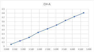
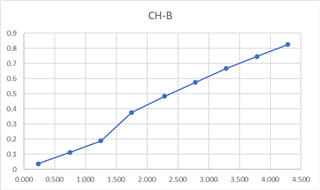
My 2nd test was to hold the voltage steady at 2.5V since I knew I had issues here and then sweep through my a current range of 1 to 17A total or approx .25A to 4.25A per shunt resistor. In this setup I see on CH-B and CH-C op-amps that I get a distinct shift in calculated gain as soon as the current goes above approx 1.5Amps for their respective shunt resistors. Before the bump and after that bump the slope of shunt current vs op-amp output stays the same but just get's an offset as I approach 1.5Amps.
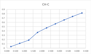
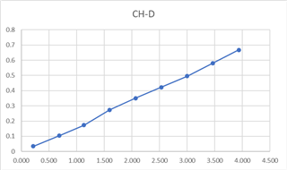
Sorry for the length of this but really wondering if anyone can see why operation becomes abnormal at 2.5 - 3V range and then within that voltage range why I would see a shift in the plot once the drop in my shunt resistor get's over about 10mV. I should mention that I've looked at the shunt resistors voltage source and did not see any significant change in noise or ripple voltage across the voltage and current loading ranges that I tests. Thanks in advance