This thread has been locked.

If you have a related question, please click the "Ask a related question" button in the top right corner. The newly created question will be automatically linked to this question.

OPA313: How to choose the Vshunt in low side bidirectional current sensing

Part Number: OPA313
Other Parts Discussed in Thread: LM324-N, TL7726

Hi,

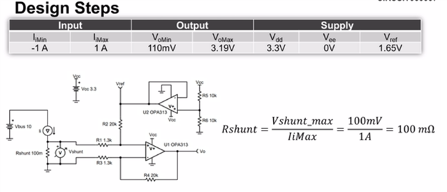
Low-side, bidirectional current-sensing circuit | TI.com Video

In this training video, I feel confused about the reason to choose Vshunt maximum as 100mV, and also confused about this part of transcript 'In low-side current sensing applications, it's common to set the maximum shunt voltage so that the load's ground potential is nearly equal to that of the op-amp and ADC.'

I have no idea about why if we choose maximum shunt voltage(100mV here) so the load's ground is equal to OP and ADC's.

Could u please help to clarify it ? Thanks! 

  • Hey Victoria,

    Adding the shunt resistor to the load makes the "ground" voltage on the load higher. You want to minimize and keep it close to the Op amp and ADC ground to keep a sufficient voltage drop across the load. With a 100mOhm shunt resistor the ground on the load will at most be 100mV.

    Best,
    Jerry

  • Hi Victoria,

    I tend to agree with you. I see two reasons why the voltage drop across the shunt should not be too high:

    1. As Jerry already mentioned the voltage drop across the shunt may be unwanted in the application because it minders Vbus and shifts the system's signal ground being connected to the upper terminal of shunt by the amount of varying voltage drop across the shunt.

    2. When the OPAmp used in the circuit is unpowered, a too high voltage drop across the shunt could damage the OPAmp or cause latch-up during the power-up. Damage can usually be prevented when all pn-junctions whether parasitic or regular do see a voltage of less than 0.3V in forward direction. And latch-up can be prevented, when the input voltage is always within the common mode input voltage range, even when powered-down. So, to be optimally safe -not only with the OPA313 but also with other OPAmps in this circuit- the voltage drop across the shunt should not exceed 100mV.

    Kai

  • Hi Kai,

    I appreciate the reply about the voltage shift in ground potential.

    Now I'm confused about the '0.3V' u mentioned and the choice of '100mV' this number. I noticed in the OPA313 datasheet, the Vcm arrange is -0.2~0.2V .Do u have any documents or reason to provide this two number? Thanks!

    BR,

    Victoria

  • Hi Jerry,

    In training video, it seems that the maximum Vshunt '100mV' is chosen first, then the value of Rshunt is calculated by 100mV. I'm confused about why to choose 100mV this number. Could u please help to clarify that? Thanks!

    BR,

    Victoria

  • Hi Victoria,

    you will find this 0.3V limit in the datasheet of  LM324-N, for instance.

    And here is a very nice appnote. See page 20:

    latch_up.pdf

    Also see the datasheet of "TL7726".

    The idea behind this 0.3V limit is that an usual pn-junction will clearly show a forward voltage drop of more than 0.3V at currents high enough to potentially become dangerous, even at elevated temperatures. So, limiting the applied voltage to <0.3V will guarantee that no pn-junction will be biased within the chip and that no insane and damaging current will flow as consequence.

    To further limit the shunt's voltage down to about 100mV has the reason to allow some headroom for noise and glitches which are always present in a real world circuit. Also, not all OPAmps show a common mode input voltage range that exceeds the supply voltages by 0.2V like the OPA313. So when using another OPAmp with a common mode input voltage range that exceeds the supply voltages by only 100mV, a shunt's voltage drop of 200mV would be too much.

    So, finally, to be on the safe side for all eventualities why not limiting the shunt's voltage drop to 100mV? 100mV is very good design practise and there's usually no reason to choose a higher shunt voltage for this sort of circuit.

    Kai

  • Hi Kai,

    Really appreciate your detailed explanation giving me more reflection on amp. Thanks! 

    BR,

    Victoria