A related question is a question created from another question. When the related question is created, it will be automatically linked to the original question.
If you have a related question, please click the "Ask a related question" button in the top right corner. The newly created question will be automatically linked to this question.
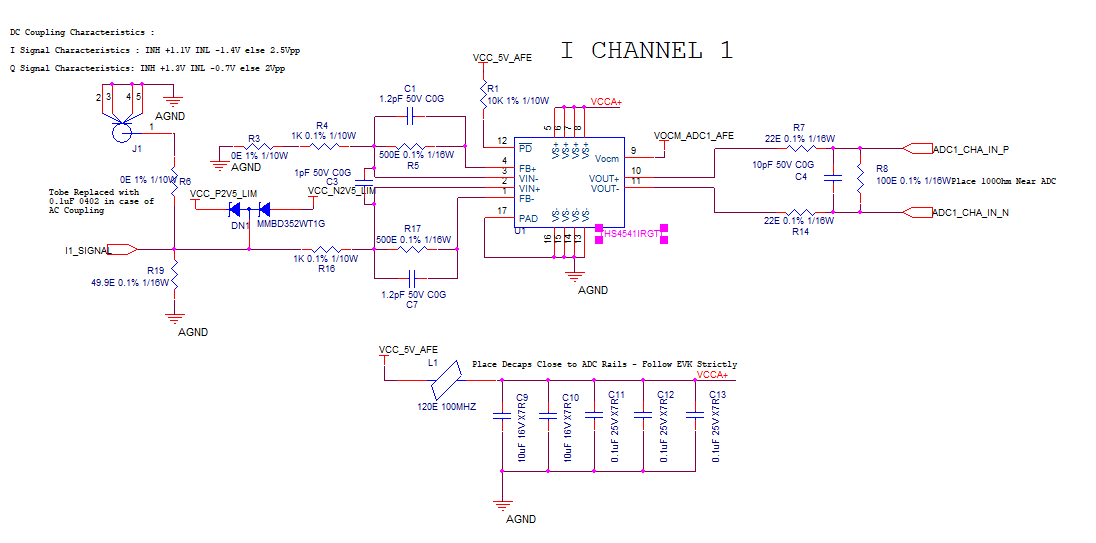
Thank you for the detailed schematic and layout snippet. One question, what is the range of the expected VOCM_ADC1_AFE? (Instead of ADC3669, is it ADC3660?)
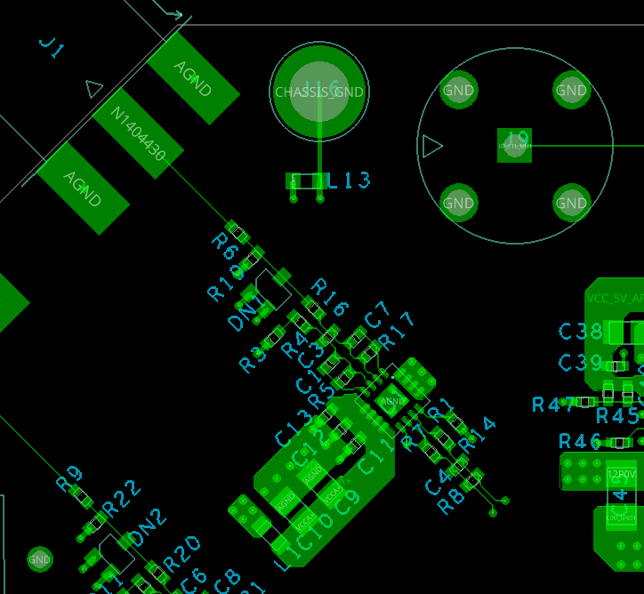
the mounting of decoupling caps is not optimal. I heavily recommend to exactly follow the layout example shown in section 12.2 of datasheet.
1. Each supply voltage pin must have the decoupling cap close by. This means that the decoupling caps must sit on both sides of the OPAmp.
2. Use four identical 100n...2µ2 / X7R caps with smallest packages (0603, 0805). Mount them exactly as shown in the layout example.
3. Don't parallel uneven ceramic caps for the supply voltage decoupling. Todays ceramic caps show ultra low ESR which can result in heavy impedance resosnances between the uneven ceramic caps. This causes the develop of impedance maxima at which the decoupling ability can totally break down. It is as if you haven't mounted a decoupling cap at all at the resonance frequency. Guess at what frequency the OPAmp will oscillate...
If you want to parallel two uneven caps, choose for the bigger cap a cap with sufficient ESR. A ceramic cap plus a tantal is a good combination, for instance. But you can also mount a 0R22 / 0603 resistor in series to the bigger capacitance, if you only want to use ceramic caps, for instance because your application runs at elevated ambient temperatures.
4. If you have several HF-OPams on the same board, I heavily recommed to use Pi-filters in the supply voltage line of every single HF-OPAmp. I always use Pi-filters in my designs.
Unfortunately, the layout example shows a mistake: It's no good idea at all to place vias in the solder pads of resistors and capacitors. This can result in severe soldering issues because the soldering tin may want to flow from the solder pad into the via (capillary effect).