This thread has been locked.

If you have a related question, please click the "Ask a related question" button in the top right corner. The newly created question will be automatically linked to this question.

TLV3601: Toggle frequency and small signal bandwidth

Part Number: TLV3601

Dear team,

For the high speed comparator, I am curious about these two question:

1. As for the comparator, actually it is the open loop amplifier inside the chip. So is the toggle frequency the GBW of the amplifier? if not, which spec can reflect the small signal bandwidth of this open loop amplifier?

2. is there any specific AC results can evaluate the consequences if the frequency of input small siganl is larger  than the toggle frequency. For example, the THD will be fallen to XX dB, the phrase margin will be decreased to XX degree?

Best regards

Wesley Huang

  • Hello Wesley,

    Yes, the "front end" (diff pair) of the comparator is similar to an un-compensated amplifier.

    The compensation cap that creates the first pole in an op-amp is also responsible for limiting the slew rate of the output.

    An uncompensated amplifier will oscillate below its required closed loop gain (under negative feedback).

    However, the output of a comparator is digital, and is not linear. The outputs are specifically designed (for a push-pull) to not go linear. As the comparator input differential voltage nears zero, the output will "chatter" on the internal noise (assuming no internal hysteresis).

    Op-amp outputs have slew rate, and comparators have rise and fall times as they should never "slew".

    When the input signal frequency starts to "overrun" the comparator, the output starts to distort, usually in a triangle-like shape with decreasing amplitude until the comparator just stops responding (output indeterminate). There also may be some added "jitter" (noise) as it nears the distortion point.

    What is happening is the output does take a finite time to transition high and low (rise and fall time).

    The comparator output will respond to the threshold crossing, but if the input signal is narrower than the rise/fall times, the output never fully transitions, and you end up with a partial "spike" or "bump" in the output as the output did not have enough time to move. In an op-amp, this would be similar to slew-rate distortion.

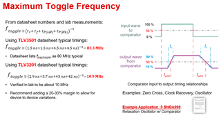
    Imagine in the graphic below, if the input wave is narrowed to the point the negative transition of the input signal line up the rise time area (tr), the output cannot fully rise during that time and the output is just a 'bump' instead of a pulse. Once the input pulse is narrower than the response times, then the output stops responding.

    The general rule of thumb is the input signal width needs to be wider than the combined  TPHL, TPLH, rise and fall times to provide a clean output.

    It is better to think in terms of period or pulse width (micro or nanoseconds), rather than frequency (Hz).

    In short - it is better not to push the comparators speed specs. If pulse fidelity and jitter is important, it is better to use a device faster than calculated, and not push a "just fast enough" device to the limits.

  • Dear team,

    Thanks for your reply.

    1. From your description, I think the toggle frequency is related to the large signal response, or limited to the "Gm" and slew rate of the amplifier.

    2. So can I understand the toggle frequency as the larger signal bandwidth of this "amplifier"?

    Best regards

    Wesley Huang

  • Hello Wesley,

    1. Yes, but the comparator does not have a defined slew rate. It becomes limited by output response times.

    2. You can. But you would not apply a signal frequency to an op-amp that is near the 0dB gain point for the same reasons - low amplitude and distortion.

    You could make the worlds worst, useless op-amp from a comparator...but don't see why you would want to when there are so many op-amp options.

    It is still better to think of the comparator in the time domain than the frequency domain.