This thread has been locked.

If you have a related question, please click the "Ask a related question" button in the top right corner. The newly created question will be automatically linked to this question.

TLV2371: Zero_crossing detection of current

Part Number: TLV2371
Other Parts Discussed in Thread: OPA381, OPA348, TLV4376, OPA380, TLV3201

Current_zero_crossing - autosave 22-12-06 18_59.TSC
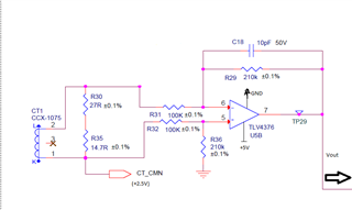
  Diff_amp.TSC

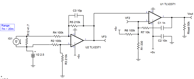
The Aim of the activity is to Add zero crossing detection to the current circuit. The Circuit shown in above figure shows output of a CT connected to Amp for current measurement. The output of which is fed to controller. This circuit is already present in the current version of the board. Nevertheless, the activity is to detect zero crossing from the Output (Vout signal)

1. How do i imitate the above circuit (figure) in tina? Have i done it correctly as shown in Diff_amp simulation file? The output seems to be 180 degrees phase shifted? is it correctly imitated?

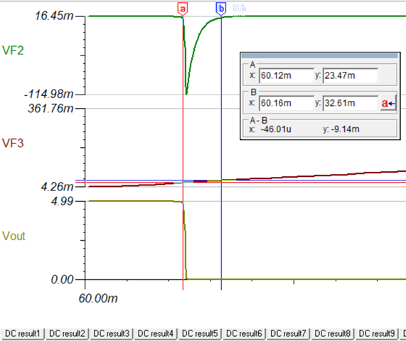
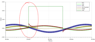
2. The output (Vout) should go to Zero-crossing input, and it should detect zero-crossing of signal. can you help with a circuit diagram.

3. I have attached simulation file (Current_zero_crossing) which i was trying for zero-crossing detection.

Please guide.

  • Hello Mohammed,

    1) swap the CT wires to invert 180 degree, to get desired phase.

    The Diff amp cuts off half of the AC input. Is this intentional? This signal won't be suitable for zero crossing.

    Zero crossing would be better with comparator. But an op amp is usually OK for such a slow frequency. The input signal should be recommend range for common mode. So the input should be higher in DC voltage so all voltages are positive. So it could be connected to CT burden resistors directly.

  • 1. CT is fixed to the board.

    2. The diff Amp is already present on previous version of the board for reading current value.

    3. The tina simulation of diff amp what i have drawn (to imitate the circuit shown in fig), is that correct?

    4. Current_zero_crossing tina file, I have set a threshold of 100mV above to detect zero crossing? is that a correct way to do it?.    Some compensation to be added by controller.

    Kindly advice.

  • Mohammed,

    I assume that the only access to the CT signal is though the half wave diff amp. Swap the zero crossing inputs to reverse phase. 

    For zero crossing to output edge change detector, add 10k to C1 to limit current when output falls. Change offset from 100mV to 15mV to better time the change. 

    It is a non ideal solution, because of the poor input signal. 

  • I didn't understand what you meant to say. Can you please share tina file for better understanding? ALso i need theory on AC hysteresis, If you can share that too, it would be much helpful.

  • Mohammed,

    I swapped the inputs to right op amp because you wanted 180 degrees from original.

    For AC hysteresis, the resistor R7 (relative to R1,R6) set the peak and R7*C1 sets the length. 

    Current_zero_crossing 12-8.TSC

  • Thanks a lot. that was much helpful.

    1. Just to be a little bit clear, I want to understand that the 180 shift, it's because of diff amp operation, right? is my understanding correct?

    you mentioned in the post that i wanted the shift? Would you be kind enough to give an explanation in plain basic terms, so that there is no confusion.

    2. the VF2 which goes down and comes back, what is the operation behind this, what actually is happening? can you please explain.

  • Also I'm using a similar circuit for detecting zero crossing on the ac side, 3phase 3-wire (delta) connection.

    Let me give you a brief about that circuit. I'm expecting review of the circuit and circuit explanation.

    3073.AC zero_crossing.TSC

    Brief: 

    VG1, VG2, VG3 are 3 phase AC source, with an input signal voltage varying from 0.5V to 3V.

    VG4, VG5, VG6 are 100mv(10KHz) added to introduce noise.

    I'm calculating zero crossing with reference to line 2(Reference) in the given circuit. The intention of the circuit is to detect line voltage zero crossing. i,e, Line voltage of V1 w.r.t V2.

    the actual circuit board (current version) has parts till OPA381. Now my new detection circuit starts after OPA381, so I'm taking input from the output of OPA381 to calculate zero crossing.

    As seen in the waveform result, I'm detecting Zero crossing at one side of the Line voltage; I'm thinking to consider this detection for zero-crossing. Will it be, Ok?

    I changed and adjusted values of resistors and cap, the circuit seems to be working fine somehow for 0.5V ~ 3V.

    But i don't know exactly how the circuit works? Let me tell a scenario, if i vary R4 less than 2.2K, let's say around 1K, and input voltage (VG1, VG2, VG3) is around 0.5V, there will be false triggering. Is it because of the noise signals (VG4, VG5, VG6) which is around 100mv, and there is no room for proper hysteresis? What happens at Vac threshold node,.....

    it's all messed up in my brain. Please explain how the circuit operation is happening with input voltages (0.5V ~ 3V) and impact of AC hysteresis at least with some nodal values

  • Mohammed,

    Now I'm confused. Your input is 0.5V yet the table is vastly different.

    How does 323V AC become 1.4455?

    Are these voltages phase to phase or phase to ground? 

  • Input range is at border levels (0.5V ~ 3V). 1.44 ~ 2.86 is very tightly packed, so for safer side i have extended range to (0.5V ~ 3V). These are phase to phase voltages, (3 wire delta in actual system). So I don't have a ground, My reference (ground) is actually line 2. For easier zero crossing detection, i have considered Line voltage of V12, which happens exactly at zero, and i'm also aware at this instant phase voltages will be 30 degrees shifted. Hope i'm clear

  • Mohammed,

    Who is the person who put U5B TLV4376 in the current zero and U2 OPA348 in the voltage zero? These two circuits make zero crossing harder to detect. They are completely unnecessary for zero cross. Can these two circuits be removed or the zero cross not be connected to them? It could be a good time to start over. 

    Attached is the voltage cross without OPA348.

    3073.AC zero_crossing (3).TSC

  • The challenge is the previous version of the board has circuit till OPA. U5B TLV4376 is not in my circuit.   So therefore, I'm left with no choice rather to take input to my zero crossing from the output of OPA. Zero-crossing circuit will be part of next version of the board. 

    Also R1, R10 cannot be grounded as circuit ground (Reference) here is line 2. Can you also mention the use of Open circuit (X) and how to use it?

  • Mohammed,

    I understand about needing to use what is already there. 

    The file "3073.AC zero_crossing.TSC" partial ignores OPA380 on one output edge where OPA380 is flat 0V. I see you have access to a different power phase (VG2,5).  Could you use that alone to determine a zero crossing phase.  

    When input signal form VG2 is large , the TLV3201 input will go well below -200mV. I'll let the comparator team comment on that. 

  • Thanks Ron for looping us in. We have been working with Mohammed on this circuit. 

    Mohammed,

    Yes, the inputs are going well below -200 mV which means you are violating input voltage range. I'll work with you offline.

  • Thanks Ron. Keep guiding.