This thread has been locked.

If you have a related question, please click the "Ask a related question" button in the top right corner. The newly created question will be automatically linked to this question.

XTR116: XTR116

Part Number: XTR116
Other Parts Discussed in Thread: TLV9052, OPA391, OPA187, TLV2186, OPA2187, OPA2186, OPA192, XTR105, OPA186

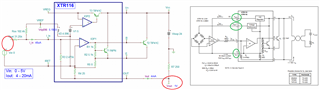
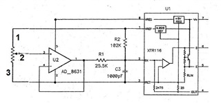
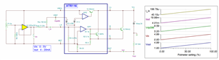
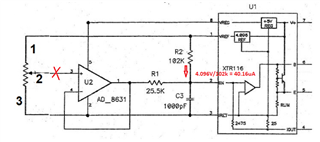
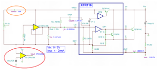
Are there any recommended circuit modifications we could make when using the XTR116U part that would allow the chip to go into an out of range mode if the input resistance (input current) was disconnected? Our circuit is currently configured similar to the Figure 1 representation on the data sheet. The issue we are currently seeing is that when any of the leads from the input resistance (current input) are disconnected the output hovers around the last output setting or goes to 20mA.

I appreciate the help.

  • Hi Matthew, 

    when any of the leads from the input resistance (current input) are disconnected the output hovers around the last output setting or goes to 20mA.

    XTR116 is a 2-wire transmitter, where two onboard voltage regulators are reference to Iret or pin3 of the IC. Can you show me the schematic which input resistance leads are discounted. 

    To have the output current goes up to 20mA, the input voltage, Vin in Figure 1 has to up to 5Vdc wrt to Iret, which means the input current is approx. 200uA (20mA/100). The current gain of the circuit is 100 A/A.  The 40uA ≤ Iin ≤ 200uA and output current is from 4mA to 20mA with the current gain of 100A/A. 

    Enclosed in the XTR116's simulation and please let us know where issues are. Maybe we will find a solution.  

    XTR116 12192022.TSC

    Best,

    Raymond

  • Hi Raymond,

    Thank you for the clarification. See example circuit image below. Disconnecting leads 1,2 or 3 or all (3) leads at once from the resistor causes the undesirable behavior.

  • Hi Matthew, 

    Disconnecting leads 1,2 or 3 or all (3) leads at once from the resistor causes the undesirable behavior.

    When the input is floating as one of leads are discounted, the output of AD8631 may go high (high input impedance). The equivalent AD8631 is TLV9052, which is simulated below. I placed 1MΩ resistor at the input and force it Iret potential in case one of input lead is discounted.  

    XTR116 12192022A.TSC

    Please let me know if the solution will work for you. 

    BTW, I do not know how accurate the V-to-I needs to be for the application. AD8631 has large Vos between 0.8mV to 4mV (TLV9052 is between 0.33mV to 1.6mV). If input accuracy is critical, I would recommend precision op amp such as OPA391 or other low cost precision op amp as the buffer. Please let me know if you need further assistant. 

    XTR116 + OPA391 12192022.TSC

    Best,

    Raymond

  • Hi Raymond,

    I just confirmed and we are actually using the OPA364AIDBVT, which is high precision as well. Would you still suggest the OPA391 as an alternate for this as well? For our use case the higher the accuracy the better. I did some sample tests with the 1Mohm resistor in place and the output drives to 4mA when a lead is disconnected. If the output went greater than 20mA or retained the last value would be the target result during this wire disconnect event.

    Do have any possible op amps in mind that could support a higher input voltage? Possibly 6-7V preferably.

    Thanks 

    Matt

  • Hi Matthew, 

    the output drives to 4mA

    Yes, the output current (with 1MΩ across the input) is going to be 4mA when input leads are discontinued per the suggested configuration (simulated behavior).  The V-I converter has a current gain 100 A/A (Iout = Iin*(2475/25 + 1).Iin is 40uA when the input leads are discounted.  

    \

    Do have any possible op amps in mind that could support a higher input voltage? Possibly 6-7V preferably.

    OPA2186, TLV2186, OPA192, OPA187, OPA2187 may be options for the replacement. The pricing on these are comparable to the cost of OPA364AIDBVT, except some of them come with dual op amp package. Below are the links that you may be find other op amp selections. 

    https://www.ti.com/amplifier-circuit/op-amps/precision/products.html#p2max=0.002;0.01&sort=p1261max;asc

    https://www.ti.com/amplifier-circuit/op-amps/precision/products.html#p2192=Zero%20Drift&sort=p1261max;asc

    If you have additional questions, please let us know. 

    Best,

    Raymond

  • Hi Matthew,

    I am going to close this inquiry. If you have additional questions, please let us know. 

    Best,

    Raymond

  • Hi Ray,

    Sorry had one additional question. Do you think possibly a FET could be incorporated that would trigger on the load disconnect event and force the output to an out of range value? Essentially I would like to try and replicate the functionality of the XTR105.

    Thanks
    Matt

  • Do you think possibly a FET could be incorporated that would trigger on the load disconnect event and force the output to an out of range value?

    What is the application? Since the typical output current is 4-20mA, you'd like to trigger a current above 20mA, say > 24mA (over or under-scale limits) when a load is disconnected. 

    If you have a comparator at the input front end, it is possible to trigger the above condition. XTR116 or XTR105 are analog input and output. XTR105 has similar output functionality as in XTR116, except the input front end (current sources convert it to voltage input). Let me know what application it is. 

    Best,

    Raymond

  • Hi Ray,

    We are using this output to determine the physical position to our control electronics. If this output goes out of range that provides an indication to our control electronics that the loop current is bad. I don't think we would want to make use of the XTR105 for our case, but employing similar type of open detection would be great.

    Thanks

    Matt

  • Hi Matt, 

    There are too lead discounted conditions. Here are couple options.

    1. Monitor the current circled in orange. 

    2. Compare the Iret potential with a comparator. (I did not. I used OPA186 op amp as comparator, see red circle). 

    3. Or use some sort of logic IC to determine the input fault state.  

    There are 3 fault conditions from your previous description and I think that the suggestion is able to meet 2 out 3 fault conditions with option 1 or option 2. You need to put a logic IC to determine all 3 conditions.  

    Please let me know if you need further assistant. 

    Best,

    Raymond

  • Hi Ray,

    Great thank you for the help. This will definitely address my issue.

    Thanks

    Matt