This thread has been locked.

If you have a related question, please click the "Ask a related question" button in the top right corner. The newly created question will be automatically linked to this question.

INA180: Input and output filters

Part Number: INA180
Other Parts Discussed in Thread: TIDA-00472, , INA241A, INA241B, INA240, INA181, OPA374

Hello,

We designed a board to drive a BLDC motor with a 16.6V 15amps supply battery.

We would like to implement Cycle by cycle current sensing for the motor and current measurements on the battery.

I looked at the reference design TIDA-00472 and saw that for current sensing it uses an op-amp and not IN-amp and that it has filters on both the input and output.

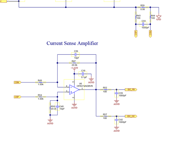
On the INA180 datasheet it states that it is best to filter the output and the input filter is only needed when output filtering is no an option.

Do I need to implement both input and output filters or just an output filter is eanough?
Also, is there a benefit to use the OP-AMP instead of the IN-AMP? (I think not bu please correct me if I am wrong).

Thanks,

Tomer

  • Hi Tomer,

    in low-side applications a differential amplifier with a simple OPAmp can do because in a low-side application no big common-mode rejection is necessary, usually.

    In a high-side application, on the other hand, a differential amplifier with a simple OPAmp will not do very probably when a high common mode rejection is necessary. Then only a current sense amplifier of the "INA" series will do. A differential amplifier with a simple OPAmp cannot provide a big common mode rejection because of the unavoidable imbalance introduced by the manufacturing tolerances, temperature drifts and long term drifts of feedback resistors. Compared to the common mode rejection of the INA180 of 100dB, e.g., a differential amplifier with a simple OPAmp will only provide 40...60dB common mode rejection. This is a huge difference.

    That it is best to filter the output and not the input is not quite true. The truth is that filtering at the inputs of INA180 can introduce a highly unwanted imbalance between the inputs caused by manufacturing tolerances, temperature drifts and long term drifts of the input filtering components and can very easily degrade the awesome common mode rejection of INA180. I have seen applications where the common mode rejection was totally ruined by the choose of unsuited input filtering components.

    So, it's wise to introduce only very soft common mode input filtering at the inputs of INA180 and to try to do the filtering mainly at the output of INA180. When it comes to the common mode input filtering the rule of thumb is: "Less is more".

    I think that differential input filtering according to figure 9-2 will make sense in many applications. But I would be very careful when adding common mode filtering (additional caps from each input to GND). The common mode filtering caps should have a small capacitance and should be made from NP0 or C0G. And, of course, they must be as equal as ever possible.

    And a low pass filter at the output of INA180 can make sense when you need a charge bucket filter for the input of an ADC.

    But hey, whether filtering is neccessary for you at all depends on your application. Without knowing your application I cannot say what filtering you need.

    Kai

  • Hello Tomer,

    Due to all the Kai mentioned we have the INA240, INA241A, and INA241B to deal with the high common mode switching.    I would suggest looking at those.

  • Thank you Kai and Javier.

    I think the INA180 is suitable for my application, no need for the INA240.

    For the motor, the PWM frequency is 10KHz so the INA180 is more than enough.

    I will follow the recommendation of filtering only the output.

    For the Battery I actually use the INA181 as it is bi-directional, here I use it to measure the charging/discharging of the battery using column counting so the accuracy is much more crucial.

    I have a very accurate ref voltage (using the TL431LIAIDBZR for that) so I believe this combination will give me the accuracy I require.

    If you have any comments, I will appreciate it.

    Best,

    Tomer

  • Hello Tomer,

    Javier is now out of the office for the holidays and will revisit this post when he returns.

  • Hi Tomer,

    if the 10kHz PWM signal contains lots of far reaching harmonics, then the use of differential input signal filtering as shown in figure 9-2 of datasheet of INA180 can make sense.

    Also keep in mind that the common mode input voltage range of INA180 allows input voltages only going down to -0.2V. So, keep the distance between the low-side shunt and the INA180 as short as possible to minimize any inducances along the shunt.

    Kai

  • Hey Tomer,

    Javier is out of the office, but I will address your questions.

    The INA180A1 (gain of 20 V/V) could replace the OPA374 (and surrounding feedback differential resistor network) because this is a DC return current configuration. The INA180A1 also has 350kHz closed loop BW and 2V/us slew rate, so it should be easy to track a 10kHz signal provided the duty cycle is not too low. For reference the OPA372 (6.5MHz unity gain BW) will have a closed loop BW of 6.5MHz/20 = 325kHz, so this is a comparable replacement.

    When it comes to ensuring high accuracy, I highly recommend performing a complete error analysis over the whole possible temperature range and shunt resistor ppm/C variation.

    https://training.ti.com/ti-precision-labs-current-sense-amplifiers-gain-error?context=1139747-1139745-1138708-1139852-1140045

    Sincerely,

    Peter