This thread has been locked.

If you have a related question, please click the "Ask a related question" button in the top right corner. The newly created question will be automatically linked to this question.

OPA192: PSRR/CMRR Test SETUP

Part Number: OPA192

Hello team,

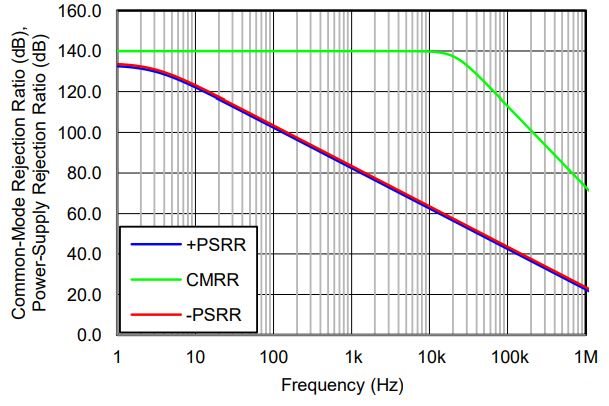
DELTA is wondering to know how to test the PSRR/CMRR to obtain likely curve below. 

We found the useful website below. but it looks it doesn't mention more detail about the setup and test method with BW.  
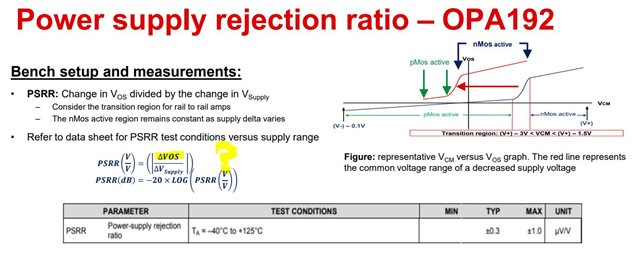
PSRR:

https://training.ti.com/power-supply-rejection-ratio-troubleshooting-guide?context=1140237-1140328-1137814-1137819


CMRR:

https://training.ti.com/common-mode-rejection-ratio-troubleshooting-guide?context=1140237-1140328-1137814-1137818

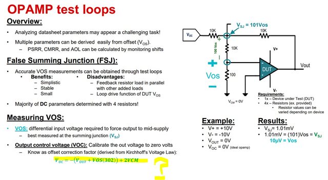
From below slide, we'd like to know how to obtain VOC formula?

From below equation of the PSRR, why it's VOS/Vsupply ? we thought it should be VOUT/Vsuuply for PSRR.

  • Hi Brian,

    Sorry for the delay, we are backed up from the holidays.  

    One thing I want to point out is that the AC CMRR and PSRR (referenced in the graph above) are not measured in the same way that the DC parameters are measured, which is the focus of the training material.  We can get the configuration of the CMRR and PSRR using the network analyzer to obtain AC data, is this Delta's goal?

    Also, typically PSRR is referenced to the input, meaning the calculated change in Vos.  The reason is because most DC changes are a result of the input stage, which will then change depending on the gain of the amplifier; i.e. - if there is 1 uV/V of psrr, then a 2 V supply change means a 2 uV Vos change, but in a non-inverting gain of 100, that will become 200 uV, vs. in a buffer unity-gain configuration, it will still only be 2 uV.

    Let me know your feedback on the first point and we will get more information to you.

    Regards,
    Mike