This thread has been locked.

If you have a related question, please click the "Ask a related question" button in the top right corner. The newly created question will be automatically linked to this question.

LM358A: How to Connect/measure Shunt Voltage from LM358/CC3220MODSF12MOBR

Part Number: LM358A
Other Parts Discussed in Thread: LM358, , TLV9062, LMV358A, TLV9002, LM7705

Hi,

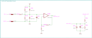
We are using CC3220MODSF12MBR and LM358AIDR to read the analog voltage, working fine.

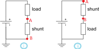
1. Now we have to measure the DC current using shunt resistor. My question is can we connect Shunt Resistor to the attached Circuit directly like, Shunt end A to AIN1 of schematic and Shunt end B to AGND1? or need additional circuit/converter? kindly advise. Shunt output will be 0-75mV.

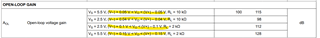
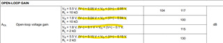
2. Also confirm, In general, what will be the accuracy we can achieve from this schematic/LM358AIDR? 

3. What will be the minimum Voltage we can measure from this circuit?

Thanks and regards,

Naveen K 

  • Hey Naveen,

    The difference between the two connections is that case 1 is low side current sensing, and case 2 is high side current sensing. I've included a blog below with a comparison of the two.

    In your case, with the LM358, the common mode voltage on the input extends to V-, so it will perform better with low side current sensing (case 1).  

    https://e2e.ti.com/blogs_/b/analogwire/posts/system-trade-offs-for-high-and-low-side-current-measurements 

    As far as accuracy, if you are sensing a shunt voltage of 0-75mV, from offset voltage alone is 5mV max over temp (6.67% error). If you add in your resistor tolerances and supply tolerance you will see additional error.

    I've included below a circuit from the analog engineer's op amp cookbook for how to design a low side current sense circuit. The op amp used is TLV9062, but you may use LM358A with considerations.

    https://www.ti.com/lit/an/sboa285/sboa285.pdf 

    Best,
    Jerry

  • Hi Jerry,

    Thank you for the information.

    1. Voltage gain is required here or we can just use Voltage follower(rail-rail) as per our circuit?

    2. Accuracy 5mV (6.67%) mean,

         a). if OPAMP V+ input is 75mV, Output VO will be 75mV±5mV (Except resistor tolerances and supply tolerance), right?

         b). if OPAMP V+ input is 3V, Output VO will be 3V±0.2V (Except resistor tolerances and supply tolerance), right?

    3. We are using two resistor in Input side(1Kohm & 150Ohm) and Two resistor in Output side(1Kohm & 1Kohm) of the OPAMP as a Voltage Divider with               1% tolerance. We can expect additional 1%+1% tolerance ? or How we can calculate additional error?

    4. Supply tolerance mean? VCC will be 3.3±0.2V, but input to output will be linear(rail-rail) right? How Supply voltage will affect to Accuracy? Kindly advise.

    Thanks and regards,

    Naveen K

  • Hi Jerry,

    Can we have your advise please.

    1. Voltage gain is required here or we can just use Voltage follower(rail-rail) as per our circuit?

    2. Accuracy 5mV (6.67%) mean,

         a). if OPAMP V+ input is 75mV, Output VO will be 75mV±5mV (Except resistor tolerances and supply tolerance), right?

         b). if OPAMP V+ input is 3V, Output VO will be 3V±0.2V (Except resistor tolerances and supply tolerance), right?

    3. We are using two resistor in Input side(1Kohm & 150Ohm) and Two resistor in Output side(1Kohm & 1Kohm) of the OPAMP as a Voltage Divider with               1% tolerance. We can expect additional 1%+1% tolerance ? or How we can calculate additional error?

    4. Supply tolerance mean? VCC will be 3.3±0.2V, but input to output will be linear(rail-rail) right? How Supply voltage will affect to Accuracy? Kindly advise.

    Thanks and regards,

    Naveen K

  • Naveen,

    The 5% value was given when provided with a 75mV input. The maximum offset is going to be referred to the input, therefore if the circuit has a gain, your offset will also be multiplied by your gain.

    If your input signal is bigger but the circuit stays in unity gain, for example 3V input. Your offset voltage will not increase, and your error will be 3V/5mV, or 0.167% error.

    1. Voltage gain will not fix offset error, your offset is multiplied by your gain.

    2. 5mV means the maximum offset is 5mV. If your input signal is 75mV, your error is 5%. If your input signal is 3V, your error is 0.167%

    3. The worst case tolerance you would see from resistors is 4%, but realistically you will see a lower error

    4. Supply tolerance means if there is ripple on the power supply, you may see some ripple passed on to the output of the device. This is measured through the PSRR, power supply rejection. If your supply is stable, with little ripple, it should not be a concern unless you are taking precise measurements. If you have a large ripple on the supply, you can either change your power supply, change your decoupling capacitor, or change your op amp to a device with better PSRR.

    Best,
    Jerry

  • Hi Jerry,

    Thank you for the information.

    1. For Precise measurements and Accuracy, we need to consider higher PSSR and Calibration and Better if we consider Unity Gain Amplifier, right?

    2.  Our Supply voltage is stable with Unity Gain Amplifier. How we can improver Offset error and additional error(Resistor/Supply tolerance)? Only by calibration in the software/Hardware preset?

    3. LMV358AIDR & TLV9002IDR, What is the minimum input sensitivity to measure and to provide output? Like, we can measure 1mV using LMV358AIDR or TLV9002IDR?

    4. As we told we are using CC3220MODSF12MOBR, What is the minimum input sensitivity for the Analog pins to measure? Like, we can measure 1mV or how much minimum voltage can be measured from CC3220MODSF12MOBR analog port?

    Thanks and regards,

    Naveen K

  • Hey Naveen,

    1. If you do not want to do calibration, your dominant error source will be your op amp offset voltage, and your resistor tolerance.
      If you calibrate for offset at time 0, then your dominant error source will be your offset drift over temp and shift over time. Drift error cannot be calibrated because drift does not behave consistently. More explanation on shift over time can be found here
    2. Offset error can be improved with calibration or with a more precise op amp.
    3. The minimum input sensitivity can be found by looking at your input common-mode voltage and your output voltage linear range, and taking the smaller value. Your linear output voltage range can be found in your open loop gain spec. Since you are in unity gain, while you may have a valid input at 1mV, you will not get 1mV on the output due to your linear output voltage range.
      For LMV358A:


      For TLV9002:


      Per the images, your linear operating range of your output can go to about 50mV from the rails.
    4. Your least significant bit is your ADC's full range voltage divided by the number of bits. The CC3220 has a 12 bit ADC, with a maximum input voltage of 1.5V, so your least significant bit is 1.5V/(2^12) = 0.3mV. 

    Best,
    Jerry

  • Hi Jerry,

    Thank you for the information.

    1. "Per the images, your linear operating range of your output can go to about 50mV from the rails."

    mean, For the voltage follower with VS=3.3V & V-=0V, we can only measure the input Voltage range from 50mV to 3.25V , right?

    2. If we want to measure 1mV input Voltage then we have to use Gain Amplifier, right?

    3. In precession Amplifier what will be the minimum Voltage can be measured with  minimum linear output voltage range? Also suggest the Precession Amplifier pin-pin compatible with LM358AIDR.

    Thanks and regards,

    Naveen K

  • Hi Naveen,

    unwanted input and output saturation effects when approaching signal ground can usually be avoided by using a small negative supply voltage. The LM7705, e.g., has been designed for exactly such applications.

    Kai