This thread has been locked.

If you have a related question, please click the "Ask a related question" button in the top right corner. The newly created question will be automatically linked to this question.

TLV3601: External hysteresis for TLV3601 in Tina-Ti

Part Number: TLV3601
Other Parts Discussed in Thread: TLV3602, TINA-TI

Hello,


I want to use an external hysteresis for the noninverting configuration of TLV3601 or TLV3602. My hysteresis voltage (V_hys) is 80mV. The hysteresis resistances are calculated based on equation (3) of the TLV3601 datasheet.

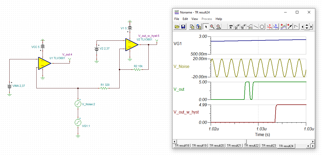
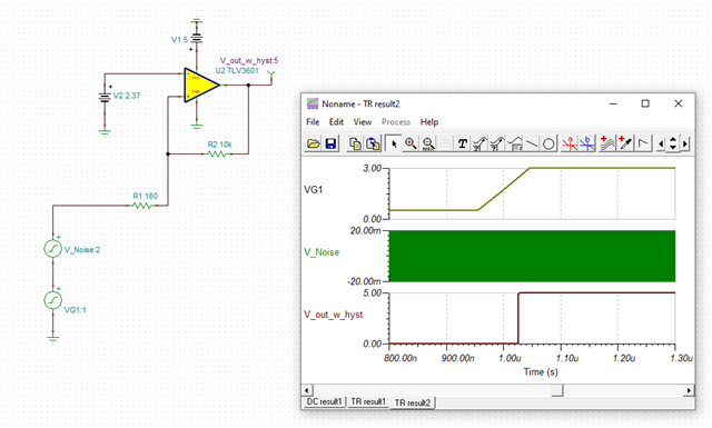
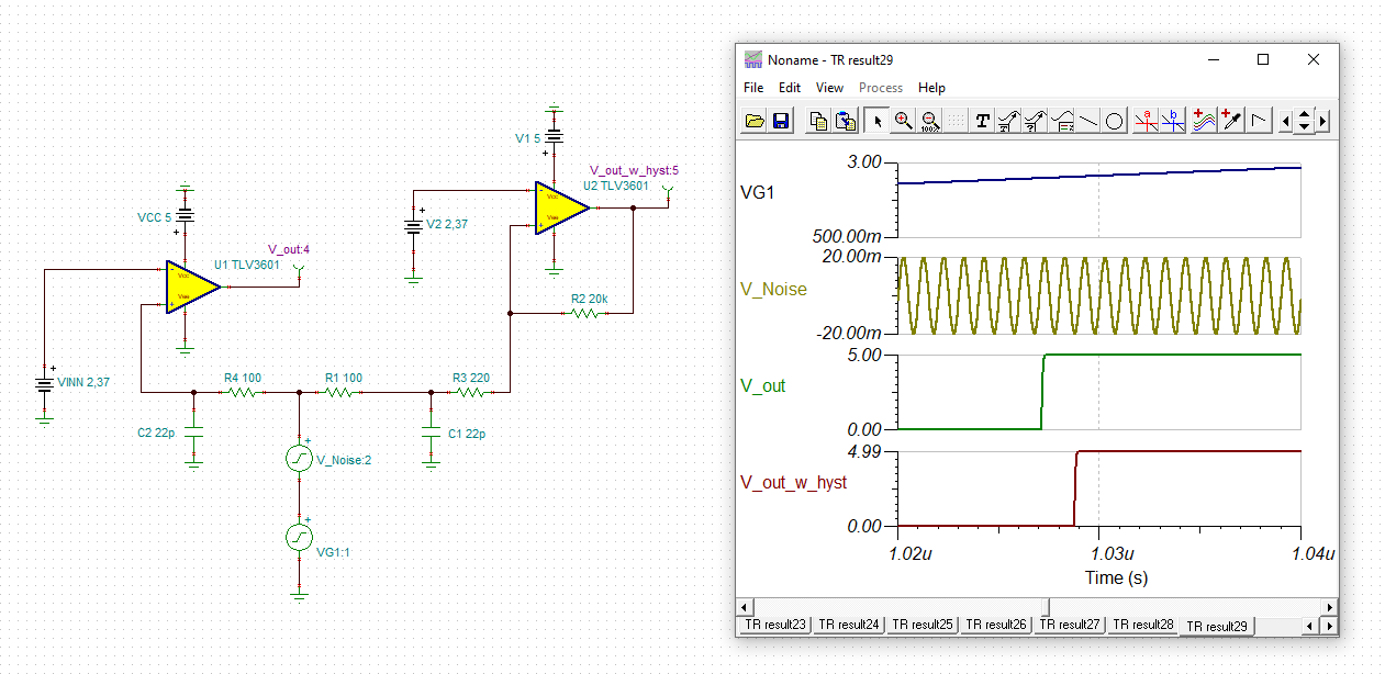
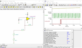
Below you can find the Tina-Ti file of my simulation circuit. Although the DC transfer characteristic in Tina-Ti shows that V_hys=80mV, the hysteresis circuit does not work in the transient analysis where the peak-to-peak noise voltage is 40mV.


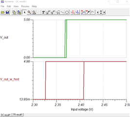
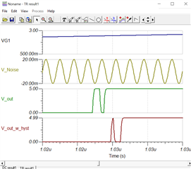
What could be the reason for this?

Best regards,

Kara

TLV3601_hys.TSC

  • Hi Kara,

    one remedy is to increase the hysteresis:

    Kai

  • Kara

    Thanks for reaching out.  Sorry this caused you some challenges.  7776.TLV3601_hys.TSCI think it is related to a setup issue in TINA.  Since you were simulating for a 2us transient window, it is recommended that you go into the analysis/set analysis parameter menu and set the max time step to 2 us / 1000.  See how I set this to 2n.  After doing this, you will see that I got the expected result as shown below.  I attached the modified file for you to use.

    Chuck

  • Another remedy is to add some low pass filtering to the input:

    The best way is to combine low pass filtering with hysteresis.

    Kai

  • Kara

    This is also a good suggestion.  Thanks Kai.  I just wanted to make sure it was clear that the error being experienced was TINA related.  

    Chuck

  • Thanks, Kai and Chuck,

    @ Kai: The value of hysteresis is critical in my application. Thus, I don't want to increase the hysteresis voltage. Using a low-pass filter with hysteresis is a good idea.

    @ Chuck: I see. I simulated the modified file. But there is still the same error. Anyway, I know there is a simulation error, and the same error will not exist in the hardware application.

    Kara

  • Hi Kara,

    it's always tricky when in your simulation signals have to be handled which are so hugely different (a wanted signal of 1MHz and a noise signal of 1GHz). So, I agree with Chuck when he says that the glitches can very well be simulation artefacts too. I would say the probability of seeing an artefact and not the real behaviour is about 50% here.

    Also, running a simulation with a 1GHz signal is rather academic because you would need to add all complex layout impedances like inductances of copper tracks, parasitic series inductances of resistors and capacitors, parasitic parallel capacitances of components and stray capacitances of the layout and the mounted components. So, don't be surprised if the performance of your real circuit differs from the simulation, if really 1GHz noise is present in your circuit. So, allthough you do not plan to increase the hysteresis up to now, you may need to do that later when problems arise.

    When you want to add low pass filtering, keep R3 always higher than R1. If possible, five times or more. C1 must not be mounted directly at the +input of comparator. This would be counterproductive because of slowing down the travelling through the sensitive and vulnerable threshold region. The idea of adding hysteresis is just the opposite, namely speeding up the travelling through the threshold region. This makes the existance of R3 so important here.

    The time constant formed by R1 and C1 and the corner frequency of low pass filtering should be above the signal frequency of wanted signal, of course. Otherwise you will see an additional and eventually unwanted delay. The corner frequency of low pass filtering is about 72MHz here and the impedance of C1 is about 7200 Ohm at 1MHz. So, the wanted signal does not see C1 and the filtering effect of C1. Only R1 and R3 appear to be present. So, the hysteresis does not change: 20k / 320 = 10k / 160.

    Since the simulation does not seem to tell the whole truth, what can you nevertheless learn from it then?

    That's always wise to use hysteresis and that it can be very helpful at add some well dosed low pass filtering. Even only the existance of a simple series resistance at the right place can do wonder: It limits current spikes running into chips and into signal ground and minimizes ground noise and ground bounce. It dampens LC-series resonances and forms a low pass filter in combination with stray capacitances.

    Having said that, filter and series resistances must not be too high when it comes to HF. Something between some dozens of Ohm and a couple of 100 Ohm usually does the trick. So, when drawing the layout of your circuit be prepared to add a series resistor here and there later.  

    Kai

  • Thank you Kai for the detailed explanation.

    Kara, I hope that this helps you with your circuit Of course, the best simulator is actually building and testing it Slight smile.  We will be closing this post if there is no further help needed.