This thread has been locked.

If you have a related question, please click the "Ask a related question" button in the top right corner. The newly created question will be automatically linked to this question.

OPA333: Higher voltage alternative

Part Number: OPA333
Other Parts Discussed in Thread: TPS7A52, , OPA187, OPA189, OPA196, OPA191, TLV9101, OPA186, OPA828

Hi,


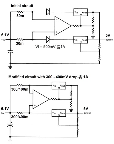
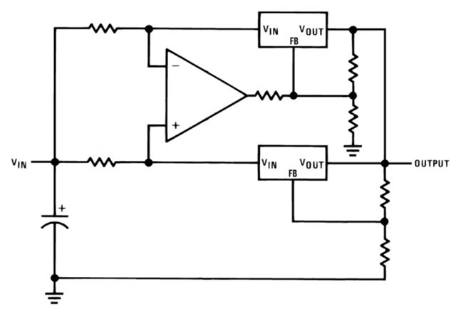
I am working on a current-sharing dual LDO power rail with two TPS7A52 LDO in parallel. I am following the instructions in the paper “6A Current-Sharing Dual LDO”


This circuit uses a OPA333 for the external control loop ensure equal distribution of the current between the two LDOs. The circuit as described has a max input voltage of 5.5V.


My design has an input voltage of 6.1V, so the OPA333 cannot be used.


I found the OPA187 and OPA 189, but I am not sure if they are an option for the circuit.


Can you please advise me further.


Thanks, Wiebren

Link to the paper with the circuit and details: https://www.ti.com/lit/ug/tidu421/tidu421.pdf?ts=1673643173469

  • See section 3.2 for how to choose.

    The amplifier is supplied by the input voltage. The OPA187 and OPA189 would not work because they do not handle inputs near the positive supply.

    Use the search function to find amplifiers with rail-to-rail inputs and offset ≤ 0.1 mV: ti.com/amplifier-circuit/op-amps/precision/products.html#p480=1;1&p1261max=6.1;180&p2max=0.002;0.1&p78=In. Use the OPA196 or OPA191.

    How much precision you need depends on the value of the two sense resistors. How much voltage drop over them can you afford?

  • Hello Clemens,

    Thank you for your reply. The value of the sense resistors is according to the paper around 30mOhm. With 3A output this will generate a drop of 45mV. This is fine for the design.

    The rail has to be as low noise as possible. Do the OPA196 or 191 meet this requirement?

    When you go to the paper; https://www.ti.com/lit/ug/tidu421/tidu421.pdf?ts=1673643173469 you will find the Electrical Schematic on page 21. I noticed that 3 100pF capacitors and 1 resistor are not populated. Do these parts have an added value to the design in your opinion? 

    Regards, Wiebren

  • Larger sense resistors reduce the relative error of the amplifier (and move some power dissipation out of the LDOs). Could you afford 330 mV?

    Amplifier offset and inaccuracies of the sense resistors do not affect the noise; the only effect is that the current sharing will deviate from the perfect 50%+50%. This effect will be larger for smaller currents, but then it does not matter as much. However, if the voltage drop over the sense resistors becomes smaller than the offset, the amplifier will try to regulate the upper LDO to less than 0% or more than 100%. Do you have a minimum output current?

    The noise is mostly determined by the LDOs themselves. The output noise of the opamp will affect the voltage of the upper LDO, but I don't know if this matters, compared to the LDO's own noise.

    C11 and C12 can reduce noise in the master and slave regulation. C4 slows down the amplifier, so it might help against input noise. I have no clue about R3.

  • Hello Clemens,


    Thank you for your reply and feedback. Yes a voltage drop of 330mV is not a problem for the design.


    The LPS7A52 has according to the graphs in the spec sheet an ideal input voltage of 5.6V. The input of the rail is 6.1V, so in the initial design I have used a rectifier to create a voltage drop and reduce the input voltage to 5.6V, see picture.


    The load will be hovering between 1.6A – 2.2A. I want to use two regulators to spread the heat over the board.


    The rectifiers can be replaced by current sense resistors. I found a suitable option which are available in 300/390/400mOhm. The available tolerance is 1% only.


    I have made a modified circuit based on sense resistors. Is this what you have in mind with the 330mV you mentioned?


    I am looking forward to your reply.

    Regards, Wiebren

  • Yes, this is what I had in mind.

    With a minimum current of about 0.8 A per LDO, the minimum voltage drop is about 240 mV, so you do not need to care about the amplifier's offset; consider the TLV9101.

  • Hello Clemens,

    Thank you for your support. I will run some simulations to see how the circuit performs.

    Regards, Wiebren

  • Hello Kai,

    Thank you for your link. Different design, but I run into the same stability issues. I have imported an OPA196 into LTSpice and with 30mOhm sense resistors the circuit (different LDOs) runs fine, but when I increase the sense resistors to 300mOhm and run a simulation with a load flips between 0.1 to 2A, the circuit start to oscillate .  

    Increasing the Rout on the opamp to 75K works with some opamps but for now not with the OPA196.

    Regards, Wiebren

  • Hi Wiebren,

    You can check out OPA186, also - it is a chopper (like 333) so drift and offset are very good, and works rail-to-rail.  I would be careful about using any amplifier that has a lower bandwidth than the 333.  

    Also, a 300 mOhm Rsns will increase the gain of the current sensing block; if you are OK with the voltage drop and power consumption then agreed a lower resolution amp. is OK.  But, keep in mind you need at least enough voltage for the drop across the Rsns as well as dropout for the LDO.

    Best Regards,
    Mike

  • Hello Mike,

    Thank you for your reply. I have checked the specs of the OPA186 and this might be the best option so far for the circuit. Problem is that I cannot find any stock of the SOT23-5 version on a short notice. Maybe you have a better view on this.

    The voltage drop is not an issue. Vin = 6.1 with no load and 6.0V with a 2A load. In my initial design I have used a rectifier before the LDO to reduce the input voltage from 6.0V to around 5.6V. 

    The rectifiers are no option with the current sharing circuit and the circuit is stable up-to 100mOhm sense resistors. A higher value leads to stability issues. Maybe the performance of the OPA186 will be better due to the 'low' Slew rate of 0.35 V/µs. 

    I am looking forward to your reply regarding the stock.
    Regards, Wiebren
  • Hi Weibren,

    Don't forget the power dissipation will be higher as the input voltage goes up.  

    It is possible that the reason for the instability is because the gain of the current measurement block is increased.  The requirement for amplifier bandwidth will go up as gain is increased.  Can you try a faster amplifier, such as OPA828, and see if stability is maintained for higher Rsns?

    I'll check on the supply situation for OPA186.

    Regards,
    Mike