This thread has been locked.

If you have a related question, please click the "Ask a related question" button in the top right corner. The newly created question will be automatically linked to this question.

TLV3502-Q1: Question about TLV3502-Q1

Part Number: TLV3502-Q1
Other Parts Discussed in Thread: TLV7034, TLV3502, LMV331-N

Hello:

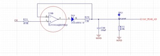
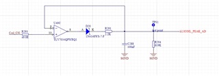
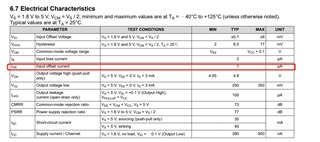
The customer designed two peak sampling circuits using TLV7034 and TLV3502 respectively, with the same parameters. However, when using TLV7034, it was found that there was a 0.01V voltage drop on the R293 resistor (the corresponding current was 0.2mA), that is, the Ios at the forward input end of the comparator reached 0.2mA, but the Ios in the specification was only 1pA. How can we understand this phenomenon?

The above phenomenon does not exist when TLV3502 is used to replace TLV7034.

  • Hi Jimmy,

    Thanks for reaching out. Do you mean IB (input bias current)? Input bias current is the current flowing out of each of the inputs of the comparator towards GND. IOS would be the difference (or mismatch) between each input bias current.  

    Regardless, 200uA is extremely high for the bias current. It is likely that the part may be damaged. Have you tried other TLV7034 samples? 

    Additionally, what is your source input voltage? Are the inputs within the common mode voltage range?

  • Hi Jimmy,

    are you sure that you want to take a comparator for the peak sampling circuit? Wouldn't you use an OPAmp for this purpose?

    The reason for destruction of the chips can be the 100nF cap which is connected to the -input: When abruptely decreasing the supply voltage, the 100nF may have stored enough energy to damage the input when discharging into the ESD cell at the -input. The same is true for the +input when you apply a voltage during the chip isn't powered. Adding current limiting resistors in series to the inputs limiting the input currents below 10mA may do the trick and prevent damage.

    Kai

  • Thanks Kai, thats a great point. 

    Jimmy,

    We will wait for your follow up.

  • Yes,the input bias current is about 0.2mA.I have tried other TLV7034 samples,the result is the same.

    The input voltage of CSI is less than 2.5V,and the supply voltage of TLV7034 is 3.3V.

  • Do you mean that an operational amplifier can be used instead of a comparator?
    I tried to change the resistance value of R251 to 10Mohm, but the voltage drop on R251 reached about 1V.
  • Hi Liuhl,

    Do you mean that an operational amplifier can be used instead of a comparator?

    Usually, an OPAmp is used in a peak detector.

    You may want to read this:

    https://sound-au.com/appnotes/an014.htm

    Is there a special reason why you take a comparator for it?

    Kai

  • There is no special reason to use comparator.I will try to use the operational amplifier to see if there is any improvement.

  • Hi Iiuhl,

    You may be better off with an op-amp.

    Op-amps have a linear output - an output that can be set to any voltage between the rails, so it can easily track the input.

    A comparator has a digital output, and is NOT supposed to be somewhere between the rails (and may even cause damage due to shoot-through if forced to go linear). The comparator digital output should be continuously "chattering" ( or "PWM"-'ing) to maintain the "analog" output. This constant chatter charging and discharging the cap will draw considerable supply current.

    Also provide a way to reset the peak - as you may get some random outputs during start-up.

    If you do want to use a comparator - the LMV331-N datasheet (page 20) shows a peak detector circuit. I would recommend a resistor in series with the emitter to limit current to prevent possibly shorting the output when the cap is reset.