This thread has been locked.

If you have a related question, please click the "Ask a related question" button in the top right corner. The newly created question will be automatically linked to this question.

OPA567: OPA567 as non inverted LED driver

Part Number: OPA567
Other Parts Discussed in Thread: TLV9161

Hello,

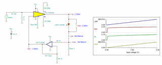
I would like to drive an LED with the OPA567 (up to 500mA). The OPA567 is wired as non-inverted OPA -> 0 ... 3,3V input. Directly at the OPA567 output (PIN 2,3) an POWER-LED is placed. After the LED, a current measuring resistor (1 Ohm) is connected to GND. A 2nd OPA, a TLV9161, is used for feedback as a non-inverting OPA to the INV-PIN (8) of the OPA567 and amplifies the measuring voltage of the current measuring resistor (V=8,25). The TLV9161 operates as a non-inverting OPA. Can I choose this circuitry. There is no negative supply voltage present.

Can I use this arrangement ( 2 x non-inverting OPV, only + 4V and GND as power supply) to ensure the level control of the OPAs.? I have concern because the OPA567 can not work near the rail boundaries?
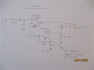
Regards

Heiko

  • Hi Heiko,

    I would run a simulation with the

    OPA567 TINA-TI Reference Design (Rev. B)

    TLV9162 TINA-TI Reference Design (Rev. A)

    (Combine both for simulating your complete circuit.)

    And because adding an OPAmp in the feedback loop adds phase lag and results in a decreased phase margin eventually causing instability, I would also run a "phase stability analysis".

    Kai

  • Hi Heiko, 

    Here is the simulation. Since I have very little information about the LED's driving frequency and BW,  I am not going to comment on the circuit. In addition, I do not have the requirements of the V-to-I conversion, rising and falling edges of the LED drivers etc.. 

    BTW, TLV9161 is GP op amp. 

    If you I_led_max = 0.4A and V_led = 2.2V, the output of the power amplifier will deliver approx. 2.6Vdc range, which it should not drive close to 4Vdc of the supply rail.   

    OPA567 Const_I LED 01182023.TSC

    As Kai suggested, the circuit will require stability compensation for the V-to-I loop, which the circuit has the stability issue currently (we need to finalize the design first). 

    If you have additional questions, please let us know. 

    Best,

    Raymond 

  • Hi Raymond,

    thanks for your answer. Please excuse my late response to your reply.

    The PWM input is set for a required LED current (LED -- LA W57B) and then is not changed for a longer time. This is a quasi static input voltage at the OPA567.

    Should phase compensation be required despite the static Qausi setpoint? -- Surely you have addressed this with respect to the lack of specification of the input frequency.

    Best regards

    Heiko

  • Hi Heiko,

    yes, even if an OPAmp only has to serve as a plain DC amplifier, it must be designed to be stable over its whole bandwidth. The reason for this the existence of broadband noise in your circuit. If there's an instability at any certain frequency, the least amount of broadband noise will drive the circuit into oscillation. It's like an instable bridge which collapses from wind: The bridge is not designed to move but rough wind can drive the bridge into a resonance catastrophe.

    By the way, another signal which contains a wide band of far reaching frequencies and can make an instable circuit oscillate is the turn-on of supply voltage.

    And another source of broadband noise is EMI hitting your circuit.

    Kai

  • Hi Heiko, 

    As Kai pointed out, there are several considerations we need to verify in order to compensate the loop stability.

    If you are concerned about posting in the information in public forum, you may send a "friendship" invitation via E2E forum, where the private messaging will not be seen by the public forum. 

    Best,

    Raymond