This thread has been locked.

If you have a related question, please click the "Ask a related question" button in the top right corner. The newly created question will be automatically linked to this question.

OPA569: Output current seemed stucking at current limit

Part Number: OPA569

Hi,

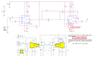
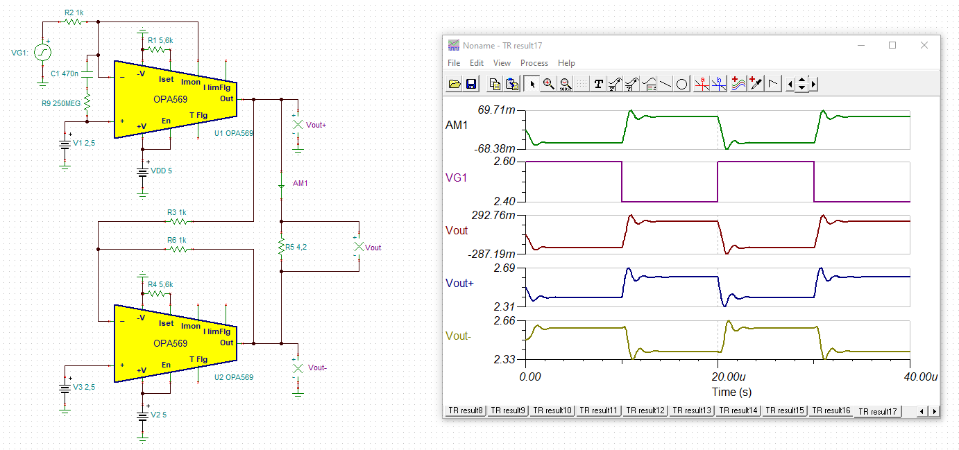
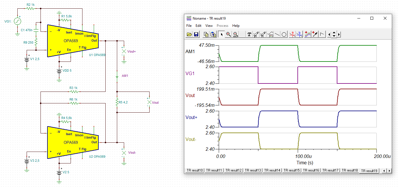
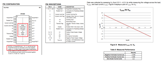
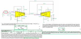
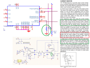
I use two OPA569‘s constructed a voltage control current source as:

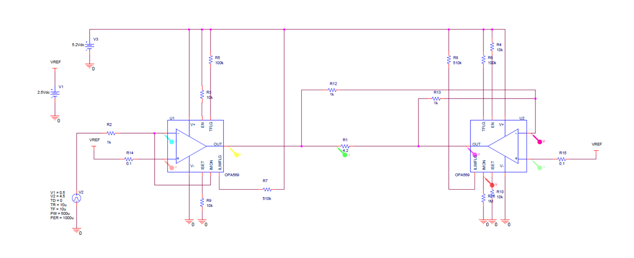
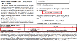
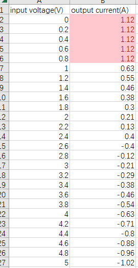
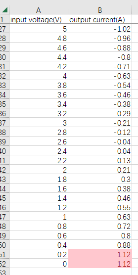
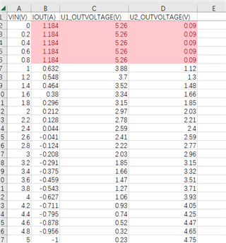
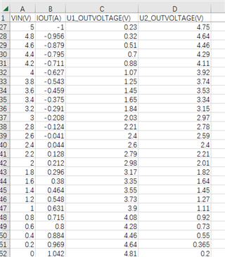
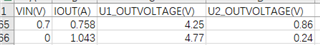
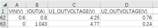
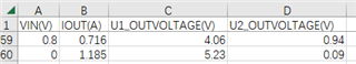
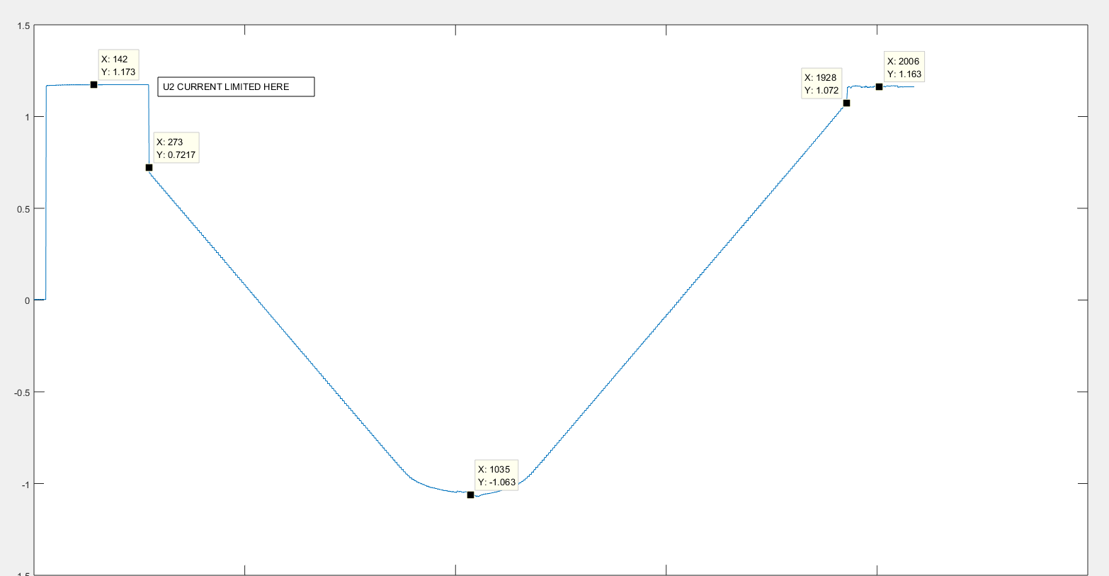
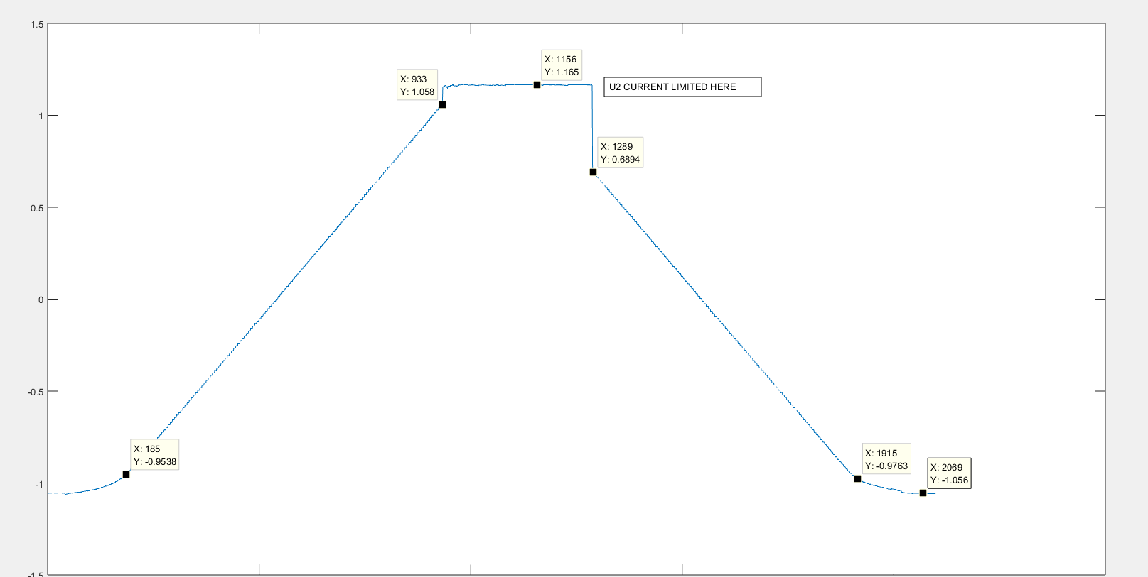
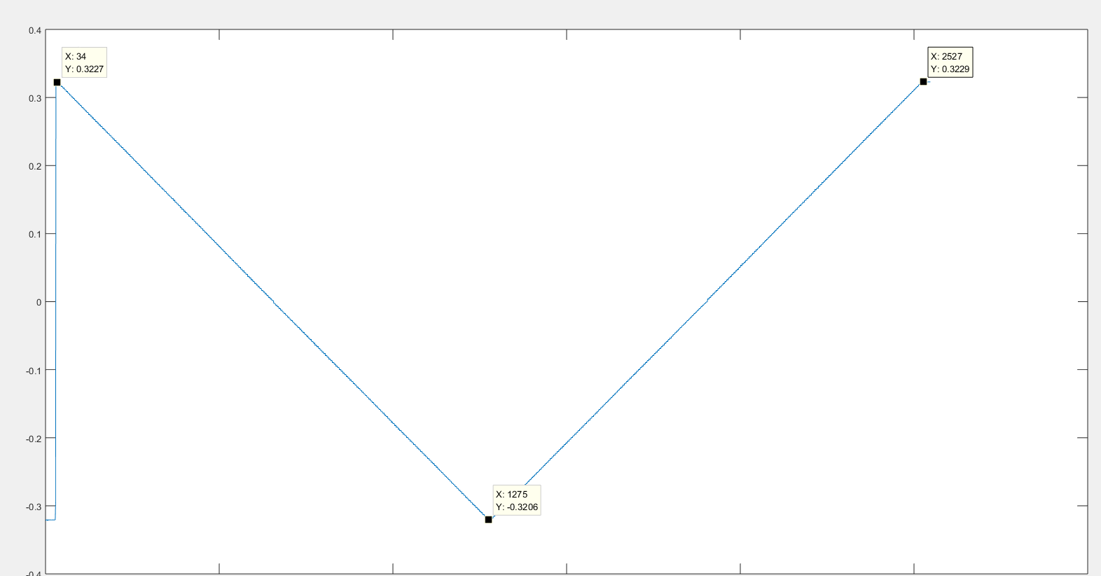
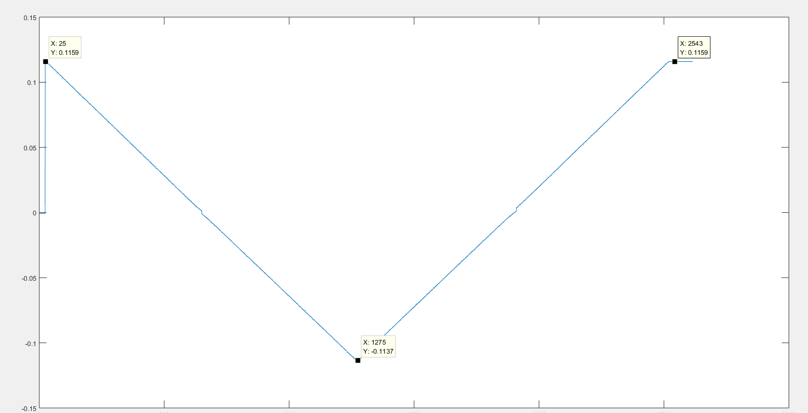
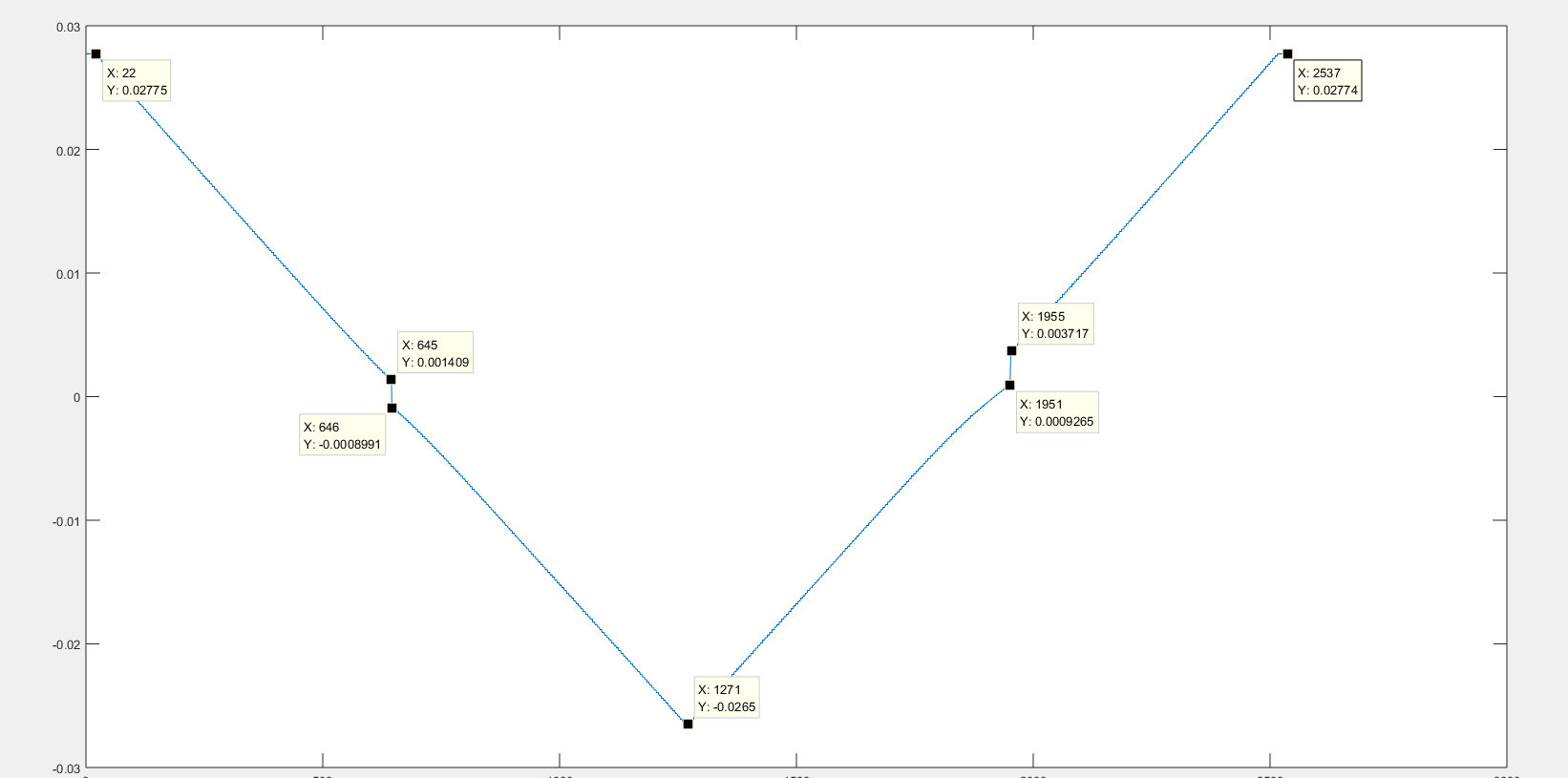
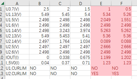
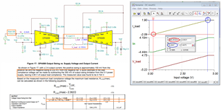
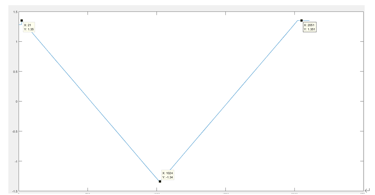
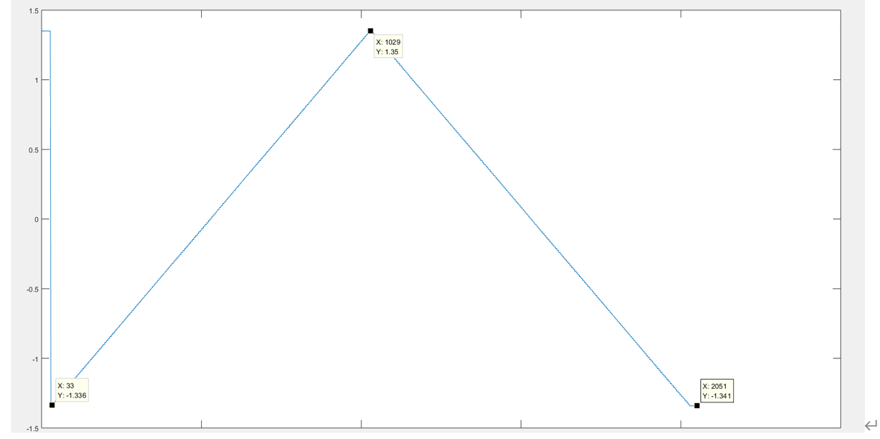
The output current limit should be 1.156A, since the Rilimit=10K. But I measured this circuit, the outpout current seemed stucked at 1.15A when input voltage between 0 and 0.4:

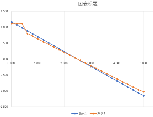
the blue line is the simulation result, orange line is the measured result.

would you please tell me where the problem is at?

THX!

Donald

  • For those reading this e2e, Donald is applying the SLAU503, TI Precision Designs: 5% Error, 0.5-4.5 V Input, +/-2 A Output, Bridge-Tied-Load (BTL) Voltage-to-Current (V-I) Converter circuit.

    Hi Donald,

    It is apparent from your measured portion of the graph that between 0 and about +0.4 V Vin the OPA569 is in current limit. Ideally the OPA569 ILIMIT would be 1.156 Amps as you have stated. However, the current limit function has positive and negative tolerances which are listed in the Electrical Characteristics table as:

    Current Limit Tolerance(7), Positive ILIMIT = 1A    ±3  typical  ±10 % maximum, Negative ILIMIT = 1A    ±3 typical  ±15 % maximum

    And keep in mind these tolerance maximums are only applicable for the stated Electrical Characteristics table conditions. The actual tolerance may be higher for the specific conditions you are subjecting the OPA569 to in your application.

    Since the ILIMIT tolerance may be introducing an unexpected error in the current limit level that you are expecting you may have to adjust the value of RSET. The 10-kilohm RSET value appears to be too high. Extrapolating your measured line to the vertical axis in a linear manner it looks like adjusting the ILIM for about 1.25 Amps should keep the particular OPA569 device out of current limit. For that case, RSET would need to be around 9.25-kilohm. I would try changing the RSET resistor for both OPA569 power op amps and rerun the graph conditions.

    Let us know what you find.

    Regards, Thomas

    TI Precision Amplifiers Applications Engineer (Retired)

  • What a nice surprise to see you back in the forum, dear Thomas Relaxed

    Kai

  • Hi Thom, 

    What a surprise to see your reply in the forum... I will see if TI can get your points' back. Relaxed

    Hi  Donald, 

    Thom has replied to your inquiry, and here is the related specification captured from the datasheet. 

    If you have additional questions, please let us know.

    Best,

    Raymond

  • Hi;

    Thank you all for the answers, I think you are right and I will try after chinese luna new year vacation. But I still wondering, the test result seemed not symmetry. When I ramped up from 0V, output stcuked between 0 to 0.4V, but I ramped down from 5V, output current keeped OK, as following:

    Could you explain the reason?

    THX!

    Donald

  • Hi Donald, 

    Could you explain the reason?

    My guess is that the right side of A2/U2 should not have current limit or have higher current limit range (smaller current_limit resistor in addition to the I tolerances). 

    Please let me know if this will resolve the issue. 

    Happy New Year!

    Raymond

  • Raymond, thank you!

    I just changed the current limit resistor from 10K to 9.1K, according to the datasheet, current limit should be:

    around 1.27A.  But actually situation seemed worse:

    Could please help me?

    Donald

  • Hi Duan,

    I see several issues:

    1. The circuit will not properly work when the input voltage is close to the supply rails, because this forces the output voltages of the both OPAmps to go into saturation. With good reason the SLAU503 uses an input voltage between 0.5V and 4.5V.

    2. The second issue is that you want to make the output current limiting to start at the same moment when the outputs of OPAmp go into saturation. This will not work.

    I would suggest to test the circuit with turning off the output current limiting. For this, replace both current limit resistors by 5k6 resistors. And allow the outputs of OPAmps to leave the saturation and to fully settle before measuring the output current versus input voltage. Otherwise you will see a third behaviour: Output voltage recovery.

    3. Also, you have omitted the Rc /Cc compensation network. This will destabilize your circuit and cause additional stability issues:

    duan_opa569.TSC

    Kai

  • takes a while to understand
  • THX,I will try again.

    Donald

  • Hi,Kai:

    1: the Rc /Cc compensation network has been added.

    2: As you mensioned, I changed the both current limiting resistor to 5.6K, but things didn't changed:

    you can see, when the control voltage ramped up from 0v, it keeped saturation until 1v. But when the control voltage ramped down from 5v, it looked normal.

    3: the results above tested as following: when power on, the control voltage is set at 2.5v, then jumped to 0v, as you can see, the output current stacked at saturation. But when I decreased the jump step to 0.7v or smaller, it looked normal:

    when the jump step large then 0.8v, saturation happened:

    Could you give me some advice?

    Donald

  • Hi Donald,

    how long are you waiting between the measurements?

    Kai

  • Hi Donald, 

    In addition to Kai's comments, I was wondering if the circuit is configured on a breadboard or similar. Did you solder the thermal pad to ground and the IC is well dissipated? 

    This app. note is verified in the lab, see the link below. 

    https://www.ti.com/lit/ug/slau503/slau503.pdf?ts=1675092446441&ref_url=https%253A%252F%252Fwww.google.com%252F

    Best,

    Raymond

  • Hi,Kai;

    I use a DAC to drive it, so just a mouse click, maybe one millisecond.

  • Hi, Raymond;

    I made a PCB to test the shematic and chip's EPAD solderd on the copper foil, beyond that, I add a heat sink under the chip. I touched the chips, the temperature is normal.

    Donald

  • Hi Donald, 

    Please change Rset from 1kΩ to 475Ω or 792Ω, and let me know if it works better. Rset determines the Vin and Iout linear ranges. 

    Best,

    Raymond

  • Hi Duan,

    I use a DAC to drive it, so just a mouse click, maybe one millisecond.

    Then your circuit may also suffer from output saturation recovery. Then it makes a difference, whether your circuit starts from output saturation or goes into output saturation. This would explain why there's a difference in your table when you start from 0V input signal or 5V.

    Anyway, you cannot expect the circuit working when the output goes and hangs into saturation. You operate the OPA569 outside of its linear operating range and specifications. Your input voltage must not go all the way down to 0V. If the circuit must work down to an input voltage of 0V, then you must add a small negative supply voltage.

    Kai

  • Hi;

    As you instructed, I rised the VC to 5.5V and ramp up and down vin between 0.5v and 4.5v, and RIMON is 750R, RLIMITis 5.6K, so current limit should be around 2A, and output current should between -1.26A and +1.26A.  results is following:

    vin ramp up from 0.5v to 4.5v and ramp down to 0.5v:

    vin ramp down from 4.5v to 0.5v and ramp up to 4.5v:

    it still suffer from the saturation.

    Besides, I noticed when output current stucked at the up current limit, U2 gone into current limit state but U1 remained normal. But at near low current limit, output current not changed linearly.

    Could you please help me to solve this problem?

    THX!

    Donald

  • this is my schematic:

  • other test results:

    RSET=3.9K,RLIMIT=5.6K:

    RSET=11K,RLIMIT=5.6K:

    RSET=47K,RLIMIT=5.6K:

    when output current is low, for example, 20ma, there is a dead zone around 0 ma. But there is not saturation.

    Donald

  • Hi Duan,

    I think that the way you carry out the measurments with the DAC which ramps fast through the input voltage range causes considerable measuring artecfacts like output saturation recovery, etc.

    I would stop testing the circuit with this DAC. Connect a simple DC voltage to the input of the circuit and measure the current by the help of a simple digital volt meter. Step by step. No fast DAC ramping which only heavily complicates the situation.

    Divide and conquer!

    Kai

  • Hi Kai,

    My DAC ramp was very slow, actually 0.05v per second, measurement took nearly 3 minutes.

    Donald

  • Hi Donald,

    I have several questions. 

    1. what 5V or 5.5V regulator you are using? How much current can the regulator source without overheating or current limiting? Please make sure that 5V LDO is able to source the current (e.g. 2A) at 5Vdc without drooping. The highest current reported in the E2E is only 1.184A.  

    2. What is the actual load? I see that WHC0630-100 inductor in series with 4.2Ω resistor? Is this 100uH inductor? 

    3. Imonitor pin19 in U2. This is bidirectional current pin (1:475 copy of the output current). The application note in Figure 20 is configured as floating node. Please remove the 750 Ω and see if it will make a difference. Otherwise, follow the datasheet's recommendation. 

    Best,

    Raymond

  • Hi, Raymont,

    1. I use a DC power supply as +5V0_VCC, which can out 3A current. It will give a warning when current exceed 3A.

    2. The inductor is 10nH, I use it to simulate the real load which is a coil.

    3. Actually I already removed the R19 but nothing changes.

    THX!

    Donald

  • I just did a new test:

    You can see at vin is below 1v, chips not work linearly.

    Donald

  • Hi Donald, 

    Here is something you can try. I think that issues are your R_load of 4.2Ω is too high and reached the op amp's output compliance voltage. You have to lower it if you want to output higher current. 

    I am doing the simulation, which is similar to what you are doing. Scan Vin from 0 Vdc to 5Vdc, and you see the linear operating region.

    OPA569 V2I converter 02012023A.TSC

    In your previous cases, the load compliance voltage is approx. 4.7Vdc and max current can be source/sink is approx. 4.7V/4.2Ω = 1.119A on 5Vdc supply rail. 

    Please let me know if you have additional questions. 

    Best,

    Raymond

  • Hi, Raymond,

    You're right. I reduced the load to 2.5 ohm, then the circuit worked perfectly:

    Thank you very much!

    Donald

  • Hi Duan,

    what exactly is your load in this application?

    Kai

  • Hi Kai;

    The load is shimming coil in NMR system.

    Donald

  • Hi Duan,

    do you know the inductance, the series resistance (winding resistance) and the self resonance frequency (caused by the winding capacitance) of this shimming coil?

    Knowing these values will improve the simualtion and lead to more realistic results.

    Kai