This thread has been locked.

If you have a related question, please click the "Ask a related question" button in the top right corner. The newly created question will be automatically linked to this question.

LM2901: LM2901PWR

Part Number: LM2901
Other Parts Discussed in Thread: TLV9032, TLV3601, TLV3201, TLV3501, TLV4376

Dear TI team,

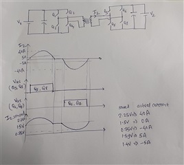
I am using comparator IC LM2901PWR for 5A and -5A resonant current detection of bidirectional CLLLC converter. Resonant current will vary from +40A peak to -40A peak and I need to detect +5A and -5A. Maximum frequency of resonant current can be upto 200 kHz.

I have added offset to sensing signal so corresponding signal to controller will be 0 to 3V (1.5V corresponds to 0A and 1.59V corresponds to +5A and 1.4V will corresponds to -5A).

I will be using circuit similar to zero cross detection circuit with Input resistor divider network (application note SNOA999).

Kindly let me know if this device will be good choice of my application (regarding speed, noise, jitter). 

Thanks,

Shritesh

  • Hi Shritesh,

    200kHz corresponds to a period time of 5µs. The response time of LM2901 is 1µs. So, the LM2901 doesn't seem to be fast enough for you application? Hard to say without seeing the full schematic and having more details on the applciation.

    Kai

  • Hi Shritesh,

    As Kai said, you would really be pushing the limits of the LM2901 speed. It's never good to push the limits of comparator speed. Speed could potentially vary ±30% across lots.

    The output would not look pretty..and would be somewhat non-symmetrical. I would use a faster comparator.

    What are the input voltages and supply voltages? What is the output driving?

  • Thanks a lot Kai for your reply. My application is for CLLLC Converter. I have attached circuit and waveform in attachment. I want to turn ON switches Q5 and Q8 when current I2 crosses +5A and turn them OFF once current falls below +5A. Also, I want to turn ON switches Q6 and Q7 when current I2 falls to -5A and turn off these switches once current rises above -5A. Sensed current is also shown in waveforms, 5A corresponds to 1.59V and -5A corresponds to 1.4V.

  • Thanks a lot Paul for your suggestions. I will use faster comparators. For my application, Input voltage to OPAMP is quasi-sinusoidal signal as shown in waveform (I2_sensed) and power supply to OPAMP is +5V and GND. Kindly let me know if comparator circuit shown in application note SNOA999 will be suitable for my application. I want to detect +1.59V and +1.4V levels in sensed circuit. I want accuracy to be within 10%, meaning I should be able to turn ON switches Q5 and Q8 when current I2 is between +4.5A and +5.5A.

  • Hi Suritesh,

    What is the ground reference? How is the +0.75 to +2.5V being created? How is the current being sensed?

    If this is truly a single supply application (GND and +5V), and the input is swinging +0.75 to +2.25 around +1.5V above ground, then you could use pretty much any high speed (<200ns) comparator. Your input overdrives are pretty high (>100mV), so the comparator should be operating at it's fastest speed.

    Do you need a single or dual? I would recommend a push-pull output for best output symmetry.

    Since you are requiring some accuracy, I would recommend looking at the TLV9032, as it has 100ns prop delay, a max offset of 1.5mV, and also does notT have built-in hysteresis, so it will trigger right at the crossing. Your signal is fast enough, and large enough that I don't think you would need hysteresis.

    Other possibilities would be the TLV3201/2 (40ns), TLV3501/2 (4.5ns), TLV3601 (2.5ns), though these high speed devices do have a mV or two of built-in hysteresis (your threshold would shift  ±1 to 2mV on the positive and negative slopes).

    Just keep in mind that the faster the comparator, the faster the crossing is reacted to, and you have more time to turn on the switch (which will probably have nF gate capacitance which can add delays).

  • Hi Paul,

    Thanks a lot for detailed explanation.

    To answer to your question "How I am getting input swinging from +0.75V to +2.25V",
    Current sensor output is varying between -0.75V to +0.75V (corresponding to -40A and +40A resp.).
    Output of this current sensor is fed to OPAMP TLV4376 with level shift of +1.5V. So, output
    from TLV4376 is varying between +0.75V to +2.25V (corresponding to -40A and +40A).
    For current sensor supply and OPAMP supply, I am using same ground.

    Dual package OPAMP is okay for me, so I have chosen precision comparator TLV9032 for analysis.
    With TLV9032, I have quickly carried out simulation in TINA (attached simulation file)

    Expected output from OPAMP U1 is +Ve pulse (+5V) for switches Q5 and Q8 when VG1 is more than 1.594 V (corresponding to +5A).

    Expected output from OPAMP U2 is +ve pulse (+5V) for switches Q6 and Q7 when VG1 is less than 1.406 V (corresponding to -5A).

    I have carried out all the calculation of resistor values keeping in mind that OPAMP is ideal (attached calculation doc).

    But, due to non-idealities of Comparator, I am getting pulse for Q5 & Q8 when VG1 is between 1.829 V to 1.24 V while I am getting pulse for Q6 & Q7
    when VG1 is between 1.169 V to 1.67 V. This is very huge error for my application.

    Please suggest me, how do I tweak resistors values to get accurate output by considering OPAMP/Comparator non-idealities.

    Thanks,

    Shritesh

    Level_Detection_circuit.docxTLV9032_Level_Detection_5A_-5A.TSC

  • Hello Shritesh,

    The model simulates typicals. The model adds the +300uV offset voltage. The over-temp max offset voltage is ±3mV,  so you need to account for that - no comparator is perfect.

    Also remember you need to take into account the prop delay at the crossing. The prop delay shifts the output back 125ns from the actual crossing.

    Note that when you simulate a long time (200us) and zoom in on a small portion (~1-2ns chunk), you loose resolution due to the time steps. So it is better to simulate a shorter time (say, 2us) and then zoom in.

    If you want to check the actual DC levels accurately, simulate at a slow speed (100's ms to seconds) to eliminate the prop delay errors.

  • Thanks a lot Paul for suggestions.