This thread has been locked.

If you have a related question, please click the "Ask a related question" button in the top right corner. The newly created question will be automatically linked to this question.

OPA863: Envelope detection of the NFC signal

Part Number: OPA863
Other Parts Discussed in Thread: OPA860, OPA615, , OPA2863

Hi Team,

Can you please help with this inquiry?

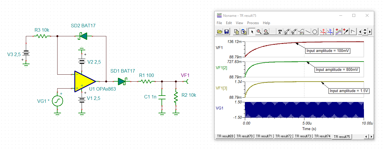
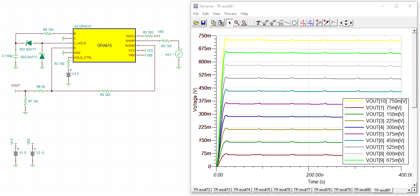
I would like to use OPAx863 for envelope detection of the NFC signal.

I found a schematic diagram (Fig. 9-3) in the datasheet but was confused with the input signal (-VBias)

Also, can I use the recommended circuit for envelope detection of the NFC signal (13.56MHz)?

Regards,

Danilo

  • Hello Danilo,

    Good question!  Peak detection is a use-case for clamping circuits containing op-amps with diodes, also known as 'DC restore' or 'DC restoration' circuits.  Beginning with brevity, the -VBias voltage present in Fig. 9-3 'clamps' or 'restores DC' to the signal by shifting the AC signal around a bias voltage.  For the particular high-speed peak detector, the clamping behavior is set by the two diodes & VBias.

    While you may have your own references or knowledge on Peak Detection, there are some TI resources and parts which contain a more description on the topic:

    https://www.ti.com/lit/ug/tidu155a/tidu155a.pdf

    The OPA615 and OPA860 are DC Restoration ICs from HSAMPs which have explanations in their datasheets.  There is likely additional TI material on 'DC Restoration' on ti.com, as well as other envelope & peak detection resources.  The following two past e2e posts also discuss this:

    https://e2e.ti.com/support/amplifiers-group/amplifiers/f/amplifiers-forum/617440/envelope-detector

    https://e2e.ti.com/support/amplifiers-group/amplifiers/f/amplifiers-forum/550168/envelope-amplifier

    Regarding the capability of the circuit in Fig. 9-3, it does appear your application bandwidth is contained inside the recommended operating conditions of the OPAx863 device.

    Please look over these resources and respond with any additional questions you may have.

    Best,

    Alec

  • Hi Danilo,

    the circuit is not very precise but should work:

    danilo_opa863.TSC

    Kai

  • Hi Alec and Kai,

    Please an earlier response of our customer below before Kai's message.

    Thank you for your generous response to my inquiry.

    Looking into your suggestions, I would first like to explain the purpose for choosing OPA863. 

    - I am planning to detect a 13.56 MHz signal with varying amplitude (for example the varying information signal might be the human pulse or sth like that).  Since my input power is limited (+3.3 V), I am considering to utilize the single supply mode of the proposed op-amp.

    - OPA2863 also has two op-amps which can be used for bandpass filtering of the carrier signal and active peak detection as shown in Fig. 9-3 of the datasheet, which reduces the overall chip area compared to OPA615.

    - Another consideration would be like my carrier signal amplitude is too high (ca. +- 15V), which need to be suppressed before passing to the op-amp operating mode.

    For all requirements, I would be grateful to you, if you could give me some insightful comments and circuit suggestions.

    Regards,

    Danilo

  • Hello Danilo,

      Please pass along Kai's message and simulation of Figure 9-3. 

      Since this design will be single supply, is the varying input signal level shifted? Even so, the signal will have to be biased to appropriate level within the amplifier's input and output voltage range throughout the design. This can be incorporated in both first and second stage. Some resources:

    1. https://www.ti.com/lit/an/sloa096/sloa096.pdf
    2. https://www.ti.com/lit/an/sboa228/sboa228.pdf
    3. https://www.ti.com/lit/an/sboa229/sboa229.pdf

       The high amplitude concern can be incorporated via a simple resistor attenuator prior to the filtering stage to a voltage range suitable for the amplifier or via active amplifier attenuator. 

    1. https://www.ti.com/lit/an/sloa163/sloa163.pdf
    2. https://www.ti.com/lit/an/sboa283/sboa283.pdf

    Thank you,
    Sima 

  • Hi Team, 

    Please see the response of our customer below.

    As Kai mentioned with the circuit, I am curious if there are any alternative circuits with more precision to fit my purpose with frequency, voltage considerations?  

    Regards,

    Danilo

  • Hello Danilo,

    I see from your response you intended to share customer feedback; is the following phrase the full summary of the customer's response:

    "As Kai mentioned with the circuit, I am curious if there are any alternative circuits with more precision to fit my purpose with frequency, voltage considerations?  "

    Does your customer have any values or metrics for their desired precision?  Could you reiterate your frequency & voltage considerations as well, especially if they have changed?

    Best,

    Alec

  • Hi Alec,

    According to our customer,

    I would prefer to obtain a sensitivity of about 50mV meaning that the change in input carrier voltage amplitude by 50mV should be reflected in the output envelope. 

    Regards,

    Danilo

  • Hello Danilo,

    Thank you for clarifying the target performance; can you share the sensitivity level or related performance you have been able to simulate/design so far?  I am not sure if you were using Kai's circuit as a starting point or setting up simulations from circuitry described in Sima's references.

    Best,

    Alec

  • Hi Danilo,

    a sensitivity of 50mV is very demanding for an OPAmp circuit. To overcome the 500mV turn-on voltage of a Schottky rectifier diode with an input signal of 50mV, the OPAmp would need an effective gain of about 10V/V at about 14MHz. Adding a linearizing gain reserve of 20dB at 14MHz would mean that a 1.4GHz OPAmp would have to be chosen to build a precise peak detector. Not even talking about the harmonics during the brief period of charging of sampling capacitor.

    And even if you find such an OPAmp, it will be hard to achieve single supply performance with a 3.3V supply voltage because sufficiently fast OPAmps do not come as rail-to-rail devices.

    The OPA615 would be able to meet your requirements referring sensitivity, but it has to be supplied with +/-5V. And don't expect ultra high precision since the OPA615 is "only" a 700MHz amplifier:

    danilo_opa615.TSC

    Kai