This thread has been locked.

If you have a related question, please click the "Ask a related question" button in the top right corner. The newly created question will be automatically linked to this question.

INA260: VBUS usage

Part Number: INA260
Other Parts Discussed in Thread: INA228

Hi expert,

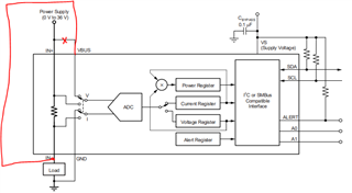
In my application, the DCDC output voltage is 0.75V and the max current is around 10A. I would like to measure the DCDC output voltage and current. The DCDC output is connected to IN+ pins and the load circuit is connected to IN- pins. In the datasheet, the VBUS pin is connected to IN+ and the measured voltage is actually on the IN+ (before the power monitor). But I want to measure the voltage on IN-, because when the output current goes to as high as 10A, the voltage drop on the power monitor could reach ~45mV (according to datasheet, the package resistance between IN+ and IN- is 4.5mOh) - this voltage drop can't be ignored comparing to 750mV output voltage.

So, I want to connect the VBUS pin to IN- instead of IN+ pin and sense the voltage after the power monitor, as the below picture showing. And then the measured voltage value is close to the real value on the load.

Could you please kindly let me know if this usage is supported? Thank you in advance!  

Best regards,

Shaoyuan Zheng

  • Hello,

    Yes, your logic is sound and doing what you are trying to do will result in the outcome you desire (measure the load voltage).

    One point of contention is you say you are trying to measure the DCDC output voltage, but then state you are interested in the load voltage. You can only do one of these things with the INA260.

    Regards,

    Cas

  • Hi Cas,

    I appreciate your reply! Sorry for the wrong description in the original thread - what we are interested in is the voltage on the load.

    BTW, could you please help to recommand the power monitor device with lower package resistance? When the DCDC output current increases to as high as ~10A, the voltage drop on the power monitor is ~45mV, which is 6% of the desired voltage on the load. We would like to ensure that the load voltage is close to 750mV. If we set the DCDC output voltage to 750mV, there is no problem on the load voltage when the output current is low, but it could drop to 705mV when the current increases to as high as 10A. So could you please help to recommand the power monitor with lower package resistance?

    In addition, is it possible to connect the IN- pin to the DCDC feadback and include the power monitor to the DCDC feadback cuicuit to erase the voltage drop impact?

    Do you have any idea to resolve the voltage drop issue please? Thank you in advance!

    Best regards,

    Shaoyuan Zheng

  • Hello,

    No need to be sorry I just wanted to point this out for clarification.

    There are no other integrated shunt parts with a digital interface.

    For your case I would consider using a digital power monitor with an external shunt. Like the INA228, 238, etc any I2C power monitor. I will leave a link below with a search on the TI website:
    https://www.ti.com/amplifier-circuit/current-sense/products.html#o7=Current/voltage/power%20monitors&p1498=Catalog&!p2192=PMBus;SPI

    (Please excuse the SPI devices as it cannot filter these out.)

    The external shunt will have the benefit of selecting the value for your application.

    The best practice would be to not add anything to the control path of the DCDC converter. It could be done, but the output of the DCDC before the current sensing "resistor" will need to be higher than 750mV and you must make sure your design can handle this.

    Are you using the INA to sense the current/ voltage to feed into a control algorithm for the DCDC?

    Regards,

    Cas

  • Hi Cas,

    Thank you for the explanation. I think I will try the device with external shunt resistor -  in this way, we can choose the shunt with lower resistance.

    Thanks again for your great support!

    Best regards,

    Shaoyuan Zheng 

  • Hello,

    No problem. If you have any other questions you can create a new thread.

    Regards,

    Cas