This thread has been locked.

If you have a related question, please click the "Ask a related question" button in the top right corner. The newly created question will be automatically linked to this question.

LMP8645: Residual voltage issue

Part Number: LMP8645
Other Parts Discussed in Thread: TPS65132

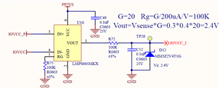
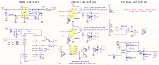
In our a project , we use LMP8645 to detect the current of DCDC output . The output voltage of DCDC is 1.8V .

LMP8645 is connected after the DCDC output .

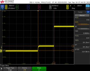
Test condition : The input of DCDC is power on , and  it's EN is off .

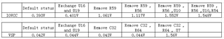
If LMP8645 is removed , the output voltage of DCDC is 0V.

But if LMP8645 is connected , the output voltage of DCDC is about 0.3V.

So we confirm this voltage is caused by LMP8645.

Could you explain why the LMP8654 cause 0.3V voltage ?

Below are the schematic and abnormal waveform :

  • Hello Jay,

    This could be from the input bias current required by the inputs.  The inputs require a few µA.  I have not worked with this part in particular but for most current sense amplifiers with this topology that is the case.  Now the issue is if the LMP8645 is creating the voltage or is the current it is drawing from something else from the circuit creating the voltage.  The reason this is important is how to mitigate the issue if this is a problem for you.  

  • Hi Javier ,

    please help to double check the following two solutions :

    Solution1, choose a current sense amplifier with a smaller input bias current .

    Solution2 , A 100KΩ resistor is connected in series before the IN+ and IN- of LMP8645.

  • Hello Jay,

    Please tell me all the parameter of interest so I can suggest another current sense amplifier.  Solution 2 will cause a large error during regular use.   

  • Hello Javier ,

    Our design goal is as follows :

    The output voltage and current of IOVCC , VSP , VSN are respectively 1.8V/0.3A , 5.7V/0.08A , -5.7V/0.08A .

    when EN is OFF , the output voltage of all three power is about 0V ; when EN is On , the output voltage of all three power are respectively 1.8V , 5.7V , -5.7V .

    Our questions:

    for this phenomenon , we still have some questions :

    when EN is OFF , we measure the output voltage of IOVCC , VSP , VSN are respectively 0.3V , 0.04V , 0.001V.

    1.IOVCC and VSP both use LMP8645 , why their residual voltage is very different ? In what circuit loop is this voltage generated ? How is this voltage derived ?

    2.Why is VSN 's residual voltage so low ? I compared the input bias current of LMP8645 and MAX9918 , MAX9918 reached 175uA , but LMP8645 only 20uA.

    Below is our entirely schematic :

  • Hello Jay,

    Below are my suspicions of the issue.  I will need to verify somethings in the lab.

    The voltage seen input of the LMP8645 or the MAX9918 depends what is on the input driving that node.  For example the LMP8645 (U16) has a IB that flows through R53 and R59 to create about 1kΩ to GND.  The IB in the datasheet is specified at 2.1V = VCM and may change with VCM voltage.  I can look at this and verify it in the lab.  This current will most likely create the lowest resistance to GND and with IB creates a larger voltage.

    This is where the impedance to GND or 0V is key.  Even though the the TPS65132A is disabled the OUTP is maybe not driven to GND but left floating and parasitically connected to GND.  This impedance could explain the difference from U16 and U19.  There could also be a different connection from VSP_P and VSN_N internal to TPS65132A that causes a different impedance to GND.   

    Regards, 

    Javier

  • Hello Javier ,

    For this issue , today I do the following test .

    Seen from the above table , there have two conclusion:

    1.When removing external impedance to ground ,LMP8645 will make a voltage of about 1.5V after power on.

    2.TPS65132 can eliminate the effects of LMP8645.

    But I still have three doubts .

    1.When removing external impedance to ground ,why will LMP8645 make a voltage of about 1.5V after power on ?

    2.Why can TPS65132  eliminate the effects of LMP8645 ?

    3.Is it theoretically possible to figure out the voltage measured in the table ?

    Thanks

    BR

    Jay

  • Hello Jay,

    1.When removing external impedance to ground ,LMP8645 will make a voltage of about 1.5V after power on.

    Javier:  This is correct.  I verified on my setup that is the case.  Internally there is something that drives to this voltage when the inputs float.

    2.TPS65132 can eliminate the effects of LMP8645.

    Javier:  This depends if it drive of the TPS65132 is strong enough to GND.  From my measurements on LMP8645 the resistance to GND should be a little under 500Ω to get the output voltage to about 400mV.  At about 50Ω I was able to get the voltage to about 30mV. 

    But I still have three doubts .

    1.When removing external impedance to ground ,why will LMP8645 make a voltage of about 1.5V after power on ?

    Javier:   This is due to internal circuitry and creating a bias point for the current to flow needed to bias the input stage.

    2.Why can TPS65132  eliminate the effects of LMP8645 ?

    Either the VSP_P or the VSN_N node is being driven to GND stronger than the other device.  When disabled the Vpos and Vneg are driven to GND according to the TPS56132.  It looks like active discharge will drive to 0V fast as for not active discharge there is a slower time for the voltage to get to zero.  

    3.Is it theoretically possible to figure out the voltage measured in the table ?

    I believe so but we do not have all the impedances to GND.  I did impedance to GND and these are the voltages I saw at the input of the LMP8645 using an EVM. 

    Resistnace to GND INP, INN voltage
    Floating 1.574V
    10kΩ 700mV
    500Ω 450mV
    100Ω 56mV
    50Ω 30mV


    Regards,

    Javier

  • Hello Javier ,

    Thank you for your proffesional reply.

    I understood this issue .

    It looks like a few minor changes are not going to solve this issue . unless I add a stroung to gnd circuit .

    But I think changing the model of current sense amplifier is a better way .

    So could you recommend a properly model ?

    Regards

    Jay

  • Jay,

    We currently do not model the floating conditions and most of our models are done for normal use case according to specifications.  Some models have extra features that cause the output to rail or give an output that is an error when operating outside of the range but not an exact replication of the device outside of the datasheet specifications.

    Regards,