This thread has been locked.

If you have a related question, please click the "Ask a related question" button in the top right corner. The newly created question will be automatically linked to this question.

OPA657: PSRR decreasing when use resisotr divider as voltage reference

Part Number: OPA657
Other Parts Discussed in Thread: LM4120,

Hi,

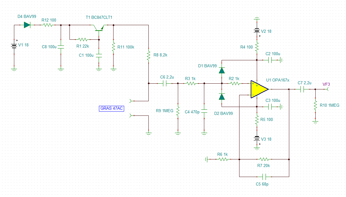
I'm waiting for the PCBA of the design discussed in the thread:

https://e2e.ti.com/support/amplifiers-group/amplifiers/f/amplifiers-forum/1183562/ths4541-opa657-ths4541-circuit-review-and-opamp-for-negative-rail

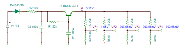
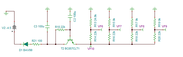
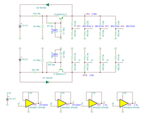
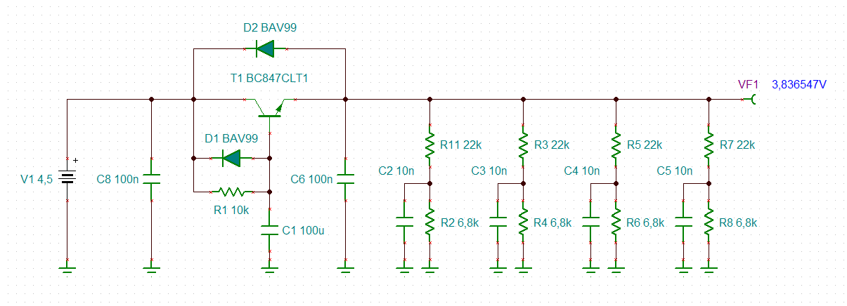
And I suddenly notice the bias reference for both TIA and FDA part:


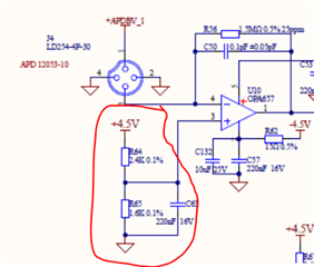
It seems the filter consisting of voltage divider has very limited PSRR performance compared with the high PSRR of the OPAmps.

Is it a better idea to use low noise reference voltage source like LM4120 or other chips you would recommend to get best SNR performance?

Thanks!

  • Hi Follin,

    take care, voltage references can generate lots of noise and can totally ruin the noise performance of your TIA. The LM4120 shows 20µVpp noise in the 0.1Hz...10Hz band. A 1k resistor, on the other hand, will only show a noise of 85nVpp in the same band.

    A two stage low pass filter may help and/or a way larger filtering time constant. If the input bias current of TIA OPAmp is too high, a low noise, low input bias current buffer can be added, best followed by an additional low pass filter.

    If the exact bias voltage plays no role, for instance because the bias voltage is also taken into consideration by an ADC, a simple capacitance multiplier arround a NPN transistor could do, as discussed in this thread:

    https://e2e.ti.com/support/amplifiers-group/amplifiers/f/amplifiers-forum/1173311/gras-47ac-preamp-circuit

    (In order to provide a voltage division, you may need to add a resistor or Z-diode in parallel to C1.)

    Capacitance multipliers are known to be ultra low noise:

    https://www.tnt-audio.com/clinica/regulators_noise3_e.html

    Kai

  • Hi Kai,

    Capacitance multiplier is really a great idea. I'm going to try it on my board.

    I have several questions:

    1) Is the "exact bias voltage" you mentioned related to the voltage drop of the current block diode and NPN since the Vbe of T1 is not a accurate/constant voltage? And I think the diode maybe removed.

    2) You said the 100uF capacitors shall be Al-cap in the thread you posted. But I have limited space so I might use Tantalum or just Ceramic (1210) capacitors. Will it affect the result a lot?  (Voltage is below 5V here)

    3)  Currently I have 8 reference voltage on one board. So  if I want to be able to adjust them individually, may I just use several voltage devider after the multiplier? For instance:

    4) I also made a negative one, is there somthing else I need to care?

    Thank you so much.

  • Hello Follin,

    For your 2nd question: you should be fine to use alternative capacitor types to Al-Electrolytic; you should be aware of the various specifications and aspects of different capacitor types.  Kai likely had good reason to recommend a specific capacitor type; my thoughts are that electrolytic makes more sense for higher capacitances due to cost.  If you would use a 1206 ceramic with the desired capacitance and rating, that might be just fine. Please investigate this for yourself if you do not have a good understanding of capacitor types & their differences.  

    Please see these additional resources also:

    Project with 'negative' capacitance multiplier for negative supply rail: https://sound-au.com/project15.htm

    Audio Xpress Article on Capacitance Multipliers: https://audioxpress.com/article/the-capacitance-multiplier

    These articles might help answer your 3rd & 4th questions.  

    I will let Kai take a try at your 1st question, as it pertains to his response.

    Best,

    Alec

  • Hi Alec and hi Follin,

    the reason why I recommended aluminium electrolytic capacitors mainly had to do with C2 and C3, to be able to mount a 100...470nF ceramic cap in parallel without suffering from antisresonances as discussed in this thread:

    https://e2e.ti.com/support/amplifiers-group/amplifiers/f/amplifiers-forum/1194027/lmh6629-high-speed-transimpedance-amplifier-for-single-photon-detection/4519200#4519200

    Also, it's difficult and expensive to get a 100µF/25V cap other than aluminium electrolytic: Tantals are very expensive and a high ceramic cap would suffer from lots of capacitance loss at a bias voltage of 18V, as discussed here. 

    https://community.infineon.com/t5/Knowledge-Base-Articles/DC-Bias-Characteristic-of-Multilayer-Ceramic-Capacitor-MLCC-KBA223633/ta-p/250035

    Of course, Follin, you can take any capacitor you want. But in order to get a large low pass filtering time constant a big capacitance would be needed. This has to do with the fact that a capacitance multiplier needs a minimum base emitter current to stay in "regulation" and R1 may not be increased all too much.

    All depends on what low pass filtering time constant you want to achieve. If a 10µF tantal is working for you, ok. But I would be careful when taking a ceramic high cap because they often suffer from a huge capacitance loss at increased bias voltages (see above) and show the very unwated microphonic effect, which means that mechanical vibrations of the printed circuit board can be transformed into AC voltages, as dissued here:

    https://e2e.ti.com/blogs_/archives/b/precisionhub/posts/stress-induced-outbursts-microphonics-in-ceramic-capacitors-part-1

    There is another issue: The circuit shown above contains the diode clamps D1 and D2  which help to protect the input of OPAmp when the supply voltage goes down. Because then C1 may store lots of unwanted charge. This can be an issue in your circuit as well. You may want to have C1 quickly discharged when the power goes down. For this scenario you have to slightly modify the circuit with the capacitance multiplier.

    To be continued...

    Kai

  • Hi Kai,

    Thank you! I learn new things. I haven't noticed the microphonic effect. I will do some test later.

    And for the protect of the input of the OPAmp, I modified the circuit a bit and so far I have the final one below.

    It seems using more components now...but I still need the opamp to avoid voltage division with the resistors around the FDA.

  • Hi  Alec,

    Yes I will try with different capacitor types. And thanks for your additional resource! I modified my circuit a bit.

  • Hi Follin,

    I should explain why my earlier capacitance multiplier was designed that way:

    The original circuit is a microphone amplifier and the first stage of a microphone amplifier and the microphone itself is often powered by a battery. When disconnecting or connecting a battery or replacing an old battery by a fresh one in the field a short-circuit or even polarity reversal can easily happen. That's why I have added D4. Because the supply voltage is with 18V rather high, the additional voltage drop across D4 would not harm.

    But D4 isolates the input of capacitance multiplier from the low source impedance of battery now. Because this may cause stability issues I have added C8. And to protect the battery from high inrush currents into C8 I have added R12.

    In your circuit there's no need for D4, I guess. And because of that you would not need R12 and C8 either. And because the low pass filtering time constant of R12 and C8 is much smaller than R1 and C1, you would not need the low pass filter formed by R12 and C8 either. Remember, R12 and C8 weren't introduced for low pass filtering but for stabilizing T1 and limiting the inrush current.

    So, you could omit D4, R12 and the big aluminium electrolytic cap C8. A simple 100...470nF for C8 should do.

    Omitting D4 would also help to decrease the voltage fluctuations at the output of the capacitance multiplier. Only the base emitter voltage of T1 would contribute to the voltage changes, but no longer D4. The voltage fluctuations are usually caused by varying loads (which is not the case in your circuit ?) and temperature changes. The expected voltage fluctuation is about -2mV/°C.

    To be continued...

    Kai

  • Hi Follin,

    I would probably do it this way:

    follin_cap_multi.TSC

    D1 helps to quickly discharge C1 when the supply voltage goes down. D1 shunts the main current arround the base collector junction of T1. The decoupling cap C8 is obligatory. Mount it close to T1. C6 is also obligatory and should also be mounted close to T1. C6 shunts HF-noise to ground which jumps across the collector emitter barrier (collector emitter junction capacitance).

    C1 can be an aluminium electrolytic or tantal. And since your application contains lots of HF, I would mount a 100nF ceramic cap (X7R) in parallel to C1 (not shown in the schematic).

    I have added a 10nF decoupling cap at each voltage divider at the output of T1. To not degrade the stability of OPA657, mount this cap close to the +input of OPA657.

    Kai

  • Hi Kai,

    Thank you so much for your detailed explanation, it's really helpful!