This thread has been locked.

If you have a related question, please click the "Ask a related question" button in the top right corner. The newly created question will be automatically linked to this question.

OPA189: Is it appropriate to use OPA189 in the signal conditioning block?

Part Number: OPA189
Other Parts Discussed in Thread: OPA192

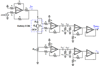
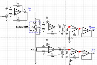
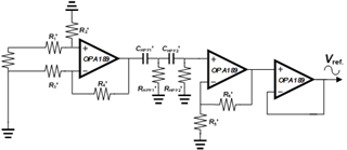
I'm currently designing a signal conditioning block to transmit signals from 1Hz to 1.5kHz using OPA189 components.

However, I'm experiencing a problem where the passed signal keeps fluctuating.

Do you know why this is happening?

Also, I was thinking about replacing the amplifier component used in the first stage's Differential Amp with an OPA192 component as a possible solution. Would this be appropriate?

(For reference, I used a 47uF capacitor and a 10M ohm resistor for the HPF.)

Could you please provide answers to two questions I have?

Thank you
  • Hi Hoonmin,

    However, I'm experiencing a problem where the passed signal keeps fluctuating.

    Can you elaborate a bit?

    Can you tell more about your application?

    Why do you need such a huge high pass filter?

    Kai

  • because i want to reject the DC voltage and transfer the 1Hz~1.5Khz Voltage signal to the next stage 

    Can i use the opa189 ??

  • Hi Hoonmin,

    Can you please provide a complete schematic showing all the RC components so we may review the circuit?

    Please elaborate on the circuit and test conditions above:

    • What is the expected amplitude range of the input signal across the shunt resistor at the difference amplifier input? What is the shunt resistor value?
    • You have mentioned you intend to use a high-pass filter to reject the DC voltage and transfer the 1Hz~1.5Khz.  What is the minimum and maximum signal bandwidth of interest?
    • What are the voltage (V+) and (V-) supplies? Are there bypass capacitors on the supplies? 
    • Are there any feedback capacitors used in the first stage difference amplifier or the second stage used for gain?
    • Is this test on a custom PCB board layout or a breadboard? 
    • On your test, where you see the output fluctuating, what is the input signal across the shunt?  Is this test with no current?  What is the amplitude/frequency of oscillation?  An oscilloscope plot could be helpful.

    Thank you and Regards,

    Luis

  • HI Hoonmin,

    I have not heard from you. I assume the issue was resolved, however if problems persist, please let us know,

    Thank you and Kind Regards,

    Luis

  • Hi Luise 

    I applogize for the delayed response. 

    • What is the expected amplitude range of the input signal across the shunt resistor at the difference amplifier input? What is the shunt resistor value?
      →Vpp = 3V 
          Shunt R = 10ohm
    • You have mentioned you intend to use a high-pass filter to reject the DC voltage and transfer the 1Hz~1.5Khz.  What is the minimum and maximum signal bandwidth of interest?
      → I want to transmit a signal in the frequency range of 1Hz to 1.5Khz, and it would be preferable if the gain remains constant over this frequency band.

    • What are the voltage (V+) and (V-) supplies? Are there bypass capacitors on the supplies? 
       V+ : 9V / V- : -9V (Rail to Rail) 
           I used a 100n bypass cap 

    • Are there any feedback capacitors used in the first stage difference amplifier or the second stage used for gain?
       No 

    • Is this test on a custom PCB board layout or a breadboard? 
       Yes Custom PCB
           (By utilizing a conversion board and implementing it on a breadboard, the signal did not exhibit any oscillation or instability)

    • On your test, where you see the output fluctuating, what is the input signal across the shunt?  Is this test with no current?  What is the amplitude/frequency of oscillation?  An oscilloscope plot could be helpful
        The signal is oscillating at the position marked by the red dot in the picture below.
  • HI Hoonmin,

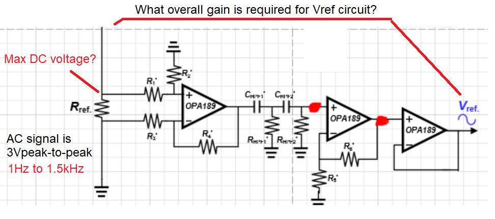
    Thank you for the information. The desired signal is 3Vp-p, with Rref= 10Ω. The OPAx189 supplies are ±9V; and desired AC signal is 1Hz to 1.5kHz frequency, constant gain is desired over this frequency. 

    - What is the frequency of the un-desired oscillation?  Is the oscillation occurring when no input AC signal is fed into the RREF shunt the resistor? Could you provide the schematics with component values?  An oscilloscope plot showing the Rref input signal and the Vref OPAx189 circuit output signal could be helpful. 

    Regarding the Vref Path:

    • What is the overall gain desired for the 1Hz to 1.5Khz AC signal on the Vref Path?
    • Maximum DC voltage on the positive side of the Rref resistor?

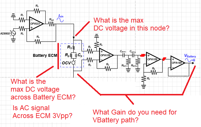
    Regarding the VBattery Path:

    • What is the max differential DC voltage across the Battery ECM?
    • What is the max DC voltage on the positive side of the Battery ECM?
    • Is the AC signal 3Vp-p on the battery ECM?
    • What gain is desired for the 1Hz to 1.5Khz AC signal on the VBattery Path?


    Thank you and Regards,

    Luis

  • Hi Hoonmin,

    when you replace the OPA189 by the OPA192 do you still see the fluctuations?

    Kai

  • HI Hoonmin,

    The OPA189 is a zero-drift  amplifier or chopper amplifier. Chopper amplifiers like OPA189 may need to match the equivalent input impedances between the op-amp positive and negative input terminals in order to eliminate the commutation of the IB spikes across unmatched input impedance.

    Since the OPA189 is a chopper, the input bias current does exhibit periodic switching transients. These input bias current transient become transformed to a voltage offset when the bias currents flow through the high value circuit resistors.  Hence, in general, we recommend to attempt to match the equivalent impedances at the inverting and non-inverting input terminals when using chopper amplifiers, as well at keeping the equivalent impedances relatively low, around the ~10kΩ range.  In addition to reducing the impedances and feedback components, adding the feedback capacitors and matching the capacitors can help improve results.

    As Kai suggested, one good option is the OPA192, which is a precision linear amplifier (non-chopper), and will not exhibit the periodic switching transients; and will be not sensitive to the impedance mismatches on the at the inverting and non-inverting input terminals.

    Nevertheless, having the component details above will also help debug the issue or propose a better circuit; since we only have a diagram with no passive component values.

    Best Regards,

    Luis

  • And the key information here would definitely be the scope plots...

    Kai

  • Hi Kai,

    Thank you,