Other Parts Discussed in Thread: TIDA-01513,
Hello E2E Experts,
Good day.
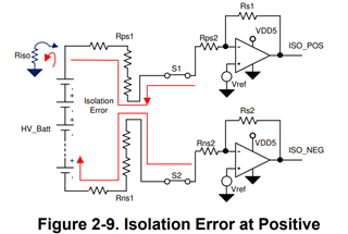
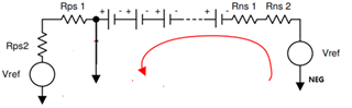
I had difficulty with the reference design TIDA-01513 - this is the result of a leakage detection system simulating the contact of the positive electrode of a high-voltage battery with low-voltage GND (as shown in Figure 2-9)
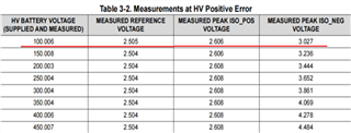
I tried to verify the conclusions in the calculation table 3-2(Riso=0 in table 3-2)
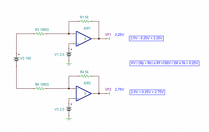
Since the error caused by the IOS and ib of the op-amp is only the voltage drop when flowing through the feedback resistor, I think that when the 2 relays are closed V_NEG = Vref+(Vref+HVbatt)/Rn * Rf/Rn, the following is my current equivalent mode and calculation process (considering the Vos effect).
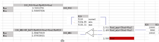
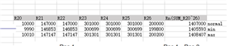
As shown in the image above, my calculation results are different from the V_Neg obtained by the TI Table 3-2 100V system, and I would like to know why...
Hopefully, someone can tell me how to calculate the worst output of an op-amp or tell me what went wrong with the above calculations, thank you.
Regards,
CSC