This thread has been locked.

If you have a related question, please click the "Ask a related question" button in the top right corner. The newly created question will be automatically linked to this question.

INA239: Inaccurate shunt values after power-reset

Part Number: INA239
Other Parts Discussed in Thread: TI-SCB

Hello,

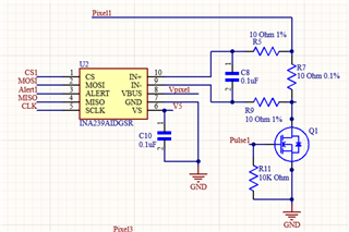
I am noticing an oddity with the IN239 where after a power-reset the shunt value readings are incorrect or shorted out. This happens for either single-shot or continuous mode for 280us conversion time and 128 averages. I can then remedy the issue by reconfiguring to 50us minimum and no averaging and then reflash my code at 280us-128avgs and it works just fine again. Any suggestions? 

Reading config register values:

config: 0x0010

adc_config: 0x06C4

Shunt_calib: 0x0FD7

diag_alert: 0xE001

Things I've tried:

1) Software power reset the INA before writing configuration values.

2) Writing zeros to the adc_config register before writing my parameters in.

3) Writing 50us no averaging into the adc_config first and then 280-128 in after.

  • Hello Isaac,

    Thank you for using the TI forum.  The INA239 does not have internal memory, so the values will will be wrong after a power reset. After powering up the device, you will need to wait for the device to turn on, then you can rewrite your configuration values. If you want the device in low power when not being used, consider putting it in shutdown mode instead of powering it off. From the values you sent above, with ADC_CONFIG = 0x06C4, the device will be in shutdown mode, which could also be part of the problem. This is also shown in the DIAG_ALERT register value you showed as 0xE001, the conversion ready flag is not on, so data is not available in the register yet. It is possible that you are reading the data too soon after starting a conversion. 

    Regards,

    Mitch

  • Hey Mitch, thanks for the speedy response. Answering the second portion first, I am currently using the shutdown mode when the device is not being asked to take a measurement. Hence the configuration I put above was during idle. the DIAG_ALERT is also set up for active low on the alert pin, so I am polling that until taken low by the INA239 before taking a measurement. I am not powering the INA off entirely in-between measurements, but if the MCU loses power so does the INA. In regards to the first part, on each power reset the MCU re-configures the INA239, and I even have the INA's read back to me there register configurations. Which seem to be the appropriate values. When I configure the INA239 at start-up for 50us conversion time and no averaging, it provides reasonable yet noisy values. But the values as posted before are given every time I set it 280us 128avg upon start-up after a power-reset.

    	do{
    		__NOP();
    		pin_state = HAL_GPIO_ReadPin(adc_handler->alrt_port, adc_handler->alrt_pin);
    		__NOP();
    	}while(pin_state);

  • Hey Isaac,

    In regards to this statement:

    I am not powering the INA off entirely in-between measurements, but if the MCU loses power so does the INA.

    Can you see if the error still occurs when you power down the INA all the way before turning it back on? It's possible that powering down the INA only partly before turning it back on could be why it is behaving abnormally. Would it be possible to power the INA independently of the MCU? This way the INA won't loose power when your MCU does.

    Regards,

    Mitch

  • I don't quite understand what you mean by powering completely down, are you referring to waiting for capacitive charges to discharge? The MCU and INA are power by a USB port, I don't have a built-in way to disconnect one or the other on the custom board. Would it be similar to do a power reset via the reset bit on the INA?

  • Isaac,

    When you said you were not powering the INA "off entirely", I thought that meant the VS was not going down to 0 all the way, so maybe 1.5V to 2V? So when i suggested powering it off all the way, I meant down to 0V. 

    After your power reset, do you still see the error if you send the reset bit to the INA before configuring the settings?

    Regards,

    Mitch

  • My apologies. Yes, I power it down completely; however, there is a small capacitive charge after disconnecting usb around 0.9V. I tried waiting for the charge to dissipate before plugging back in, but this did not resolve the issue. I also have the same error if I send the reset bit to the INA before configuring the chip.

  • Hey Isaac,

    Ok, interesting....  I will see if I can reproduce the error....  does this only happen when power resetting from 280µs conversion time and 128 averages? (ie, have you tried other settings). Also, does this happen when you do a reset on the device without power cycle?

    Regards,

    Mitch

  • Hey Isaac,

    We were not able to reproduce the issue you are seeing. In addition to my questions above, do you see this with multiple devices, or just the one?

    Regards,

    Mitch

  • I tried another board and got the same result. When I start the board up,  I get shorts & random numbers after configuring for 280us and 128 avgs and requesting conversions. From the data snapshot you can see the timeline of the "reflashing config trick". If I then change the conversion back to 50us no averaging, then return to the desired configuration It provides rather accurate values. From the schematic, I turn on the mosfet before reading, transients, to my knowledge, wouldn't cause this issue. Bus voltage stays accurate.

    From reading back configuration:

    config address: 0x0010

    adc_config: 0x06C4

    Shunt: > 0

    diag_alert: 0xe001

    When I request a conversion I set the adc_config value to single shunt conversion.

    void read_shunt_voltage(INA239_handler *adc_handler){
    	GPIO_PinState pin_state;
    	/*COMMAND FOR SINGLE SNAP SHOT*/
    	HAL_GPIO_WritePin(adc_handler->pulse_port, adc_handler->pulse_pin, GPIO_PIN_SET); 	// Turn on the GaN FET
    	adc_handler->mode = SINGLE_SHUNT_VOLTAGE_MODE;
    	uint16_t adc_config_vals = (adc_handler->mode << MODE_BITS) |
    							   (adc_handler->us_bus_vol << VBUSCT_BITS) |
    							   (adc_handler->us_shunt_vol << VSHCT_BITS) |
    							   (adc_handler->us_temp_meas << VTCT_BITS) |
    							   (adc_handler->averaging << AVG_BITS);
    
    	// Serialize tx buffer for write of the adc cmd
    	spi_tx_buffer[0] = __WRITE(ADC_CONFIG_ADDR);
    	spi_tx_buffer[1] = adc_config_vals >> 8;
    	spi_tx_buffer[2] = adc_config_vals;
    //
    	HAL_GPIO_WritePin(adc_handler->cs_port, adc_handler->cs_pin, GPIO_PIN_RESET);		// Take chip select line low for COM
    	HAL_SPI_Transmit(adc_handler->hspi, spi_tx_buffer, 3, 100);							// Transmit tx buffer data
    	HAL_GPIO_WritePin(adc_handler->cs_port, adc_handler->cs_pin, GPIO_PIN_SET);			// Take chip select line high
    
    	/*Wait for ALERT pin to go high signaling conversion of current read is ready*/
    	spi_tx_buffer[0] = __READ(DIAG_ALRT_ADDR);
    	do{
    		__NOP();
    		pin_state = HAL_GPIO_ReadPin(adc_handler->alrt_port, adc_handler->alrt_pin);
    		__NOP();
    	}while(pin_state);
    
    	HAL_GPIO_WritePin(adc_handler->pulse_port, adc_handler->pulse_pin, GPIO_PIN_RESET); // Turn Off GaN FET
    
    	spi_tx_buffer[0] = __READ(VSHUNT_ADDR);	// Prep tx buffer with read of current meas addr
    
    	HAL_GPIO_WritePin(adc_handler->cs_port, adc_handler->cs_pin, GPIO_PIN_RESET);	// Take chip select line low for COM
    	HAL_SPI_Transmit(adc_handler->hspi, spi_tx_buffer, 1, 100);		// transmit read command
    	HAL_SPI_Receive(adc_handler->hspi, spi_rx_buffer, 2, 100);		// read in response
    	HAL_GPIO_WritePin(adc_handler->cs_port, adc_handler->cs_pin, GPIO_PIN_SET);	// Take chip select line high
    
    //	float temp = 1000000*convert_raw_ina_reading(spi_rx_buffer, 's'); //uV with two dec of precision
    	uint32_t temp = 0;
    	for(int i=0; i < 4; i++){
    		temp = (temp << 8) | spi_rx_buffer[i];
    	}
    	adc_handler->shunt_voltage_value = temp;
    }

  • Hey Isaac,

    During a time when you are not getting any shunt voltage, could you measure the voltage difference at the input pins to the device to confirm that there really is current running?

    Regards,

    Mitch

  • Hey Mitch,

    I wanted to first say thank you for the dedication in helping solve this issue. I checked the voltage across each of the 4 shunt resistors and I am getting good voltage readings on the fluke during a time when the INA is reading bad shunt readings.

  • Hey Isaac,

    You're welcome! Do you by chance have an INA239EVM to see if you can reproduce the issue on it? 

    Mitch

  • Or even just using the GUI/Firmware for the EVM on your setup to see (by connecting the TI-SCB SPI lines to your hardware), to rule out any possibility of a firmware issue. 

  • Follow up question. On the diag_alrt register, do I want both the SLOWALERT bit and CNVR bit both to be high to get a alert pin action once a completed averaged value is ready? Or is it one OR the other bit depending on whether I want an averaged value or not?

  • The CNVR bit is what you set to get an alert on the alert pin when an averaged conversion is ready. the SLOWALERT is used for the threshold alerts (such as SOVL or SUVL), to choose if you want to alert on individual conversions or the averaged conversion value. 

  • Hey Isaac,

    Did you see my questions above about using the SCB or EVM to try to reproduce the error in your system?

    Regards,

    Mitch