This thread has been locked.

If you have a related question, please click the "Ask a related question" button in the top right corner. The newly created question will be automatically linked to this question.

OPA548: Whether OPA548 are suitable for driving inductive coil

Part Number: OPA548
Other Parts Discussed in Thread: , ALM2403-Q1

Hi, guys

Sorry to bother, I have searched some of the posts about using speaker amplifier beyond audio application, but I can't find solutions to mine.

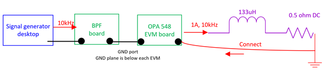
My application is to drive inductive coil load (Helmholtz coil). 

Input Signal: frequency sweep 1kHz-100kHz sinewave, voltage signal

Output Signal:  1kHz-100kHz sinewave, 0.1A

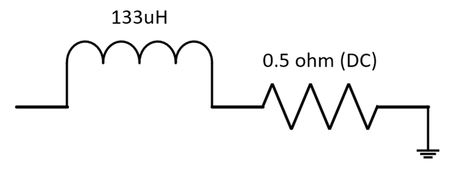
Load:  L of the coil =133uH,  DC resistance of coil is 0.5 ohm. 

Because what we want is flow a certain know current in the coil to generate the magnetic field (magnetic field is only related to the current in the coil, e.g. 0.1A, 0.2A) we don't care the voltage in the coil. My question is 

My question is:

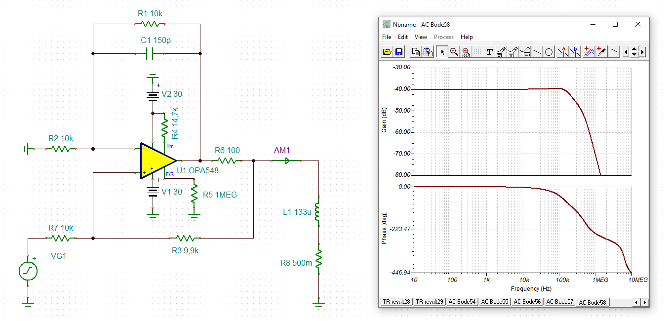
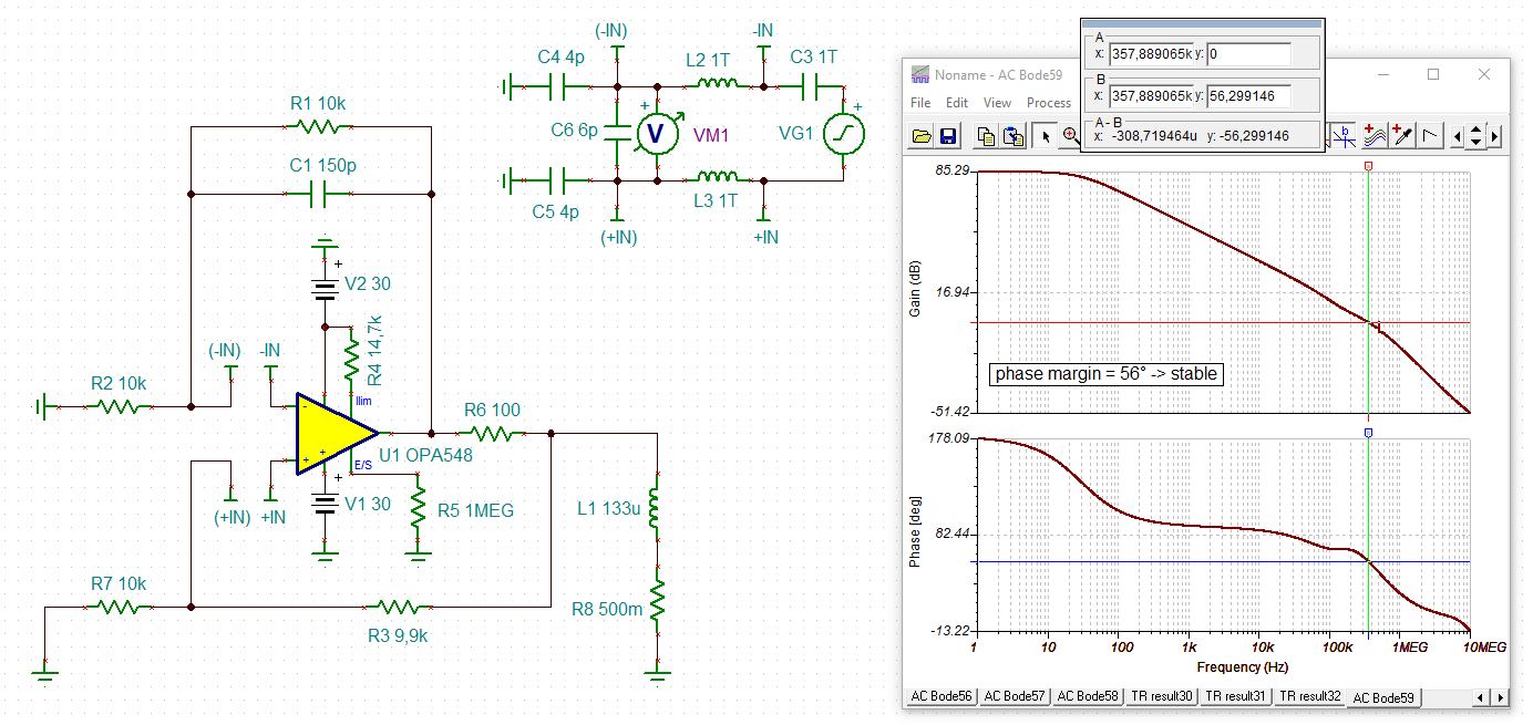
Q1 Stable Problem: Can power amplifier directly drive the inductive coil (there many kinds of amplifier that can produce high current, e.g. OPA548)? I know for capacitive load we need to compensate the phase margin, but for indutive load I rarely see any material, it seems that we can directy connect it?

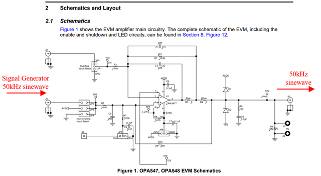
Since I not familiar with power operation amplifier design, so I want to buy the evaluation board OPA548EVM directly. Can I just connect the signal generator and feed the sinewave to this evaluation board? Using inverting/non inverting/ Howland configuration?\

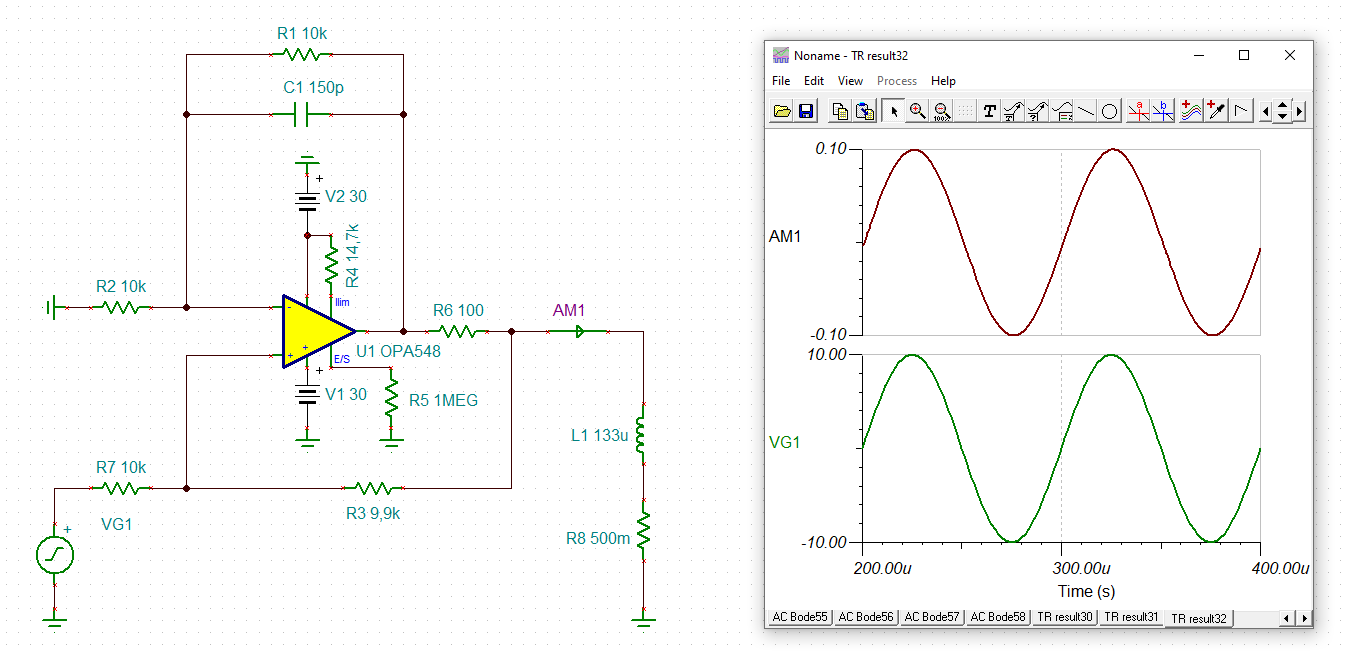
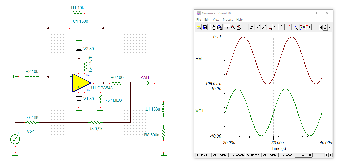
Q2 : Since I want to sweep frequency from 1kHz-100kHz, 0.1A. For example, at 100kHz, the impedance of L is 84 ohm, so 0.1A×84 ohm = 8.4V<10V max of OPA548? As long as the OPA 548 output voltage range and slew rate are not exceeded? 

Best Regards

Grant Ward

  • Grant,

    1. I looked at the device in a non-inverting configuration.  In your post you mention a few different configurations, so if you want to re-do the analysis for a different configuration let me know.
    2. The stability is impacted somewhat by the inductor.  You are correct that this isn't covered in much literature.  Perhaps this is something we should write up for general usage.
    3. I did the stability two different ways:
      1. open loop stability test
      2. closed loop AC response test
    4. The stability analysis methods are documented here: Amplifier Stability Series 
    5. In a buffer configuration the phase margin is 32deg.  Ideally we want 45deg of phase margin.  In some cases engineers will find 32deg acceptable, but I recommend trying to improve this further.
    6. One simple approach to improving phase margin is to use gain.  I ran the same simulations in a gain of 5.  The phase margin improved to 62 deg.  If using gain is  not an acceptable approach for your application we can consider other alternatives.
    7. Here is a presentation showing the results: opa548-stability-inductive load.pptx
    8. One precaution for inductive loads is that they will tend to have a high voltage kickback when power is cycled off.  For this reason, you will need to have external protection diodes to protect the amplifier output from damage.  The EVM has these diodes include in the design, so you can use this in your initial prototype.  I think testing this on the EVM is a good idea.
    9. I think this is a good starting point.  Let me know how you want to modify the circuit for your particular needs and we can re-do simulations to confirm stability.

    Best regards, Art Kay 

  • Hi Art Kay

    I am really appreciated that you provide such a detailed explaination and very easy-undestand answer and simulation. Also very appreciate your reminder about inductive load's kickback. Now I know how to analyse the phase margin by simulation on my own. 

    A little question about ground:

    At first I am trying to drive the inductive coil in diffrential mode. But since most power opearation amplifier is single end output. So I turn to single end connection.

    Another my application is drivng the coil at 1A or even more current. But I face the GND problem. Black dot are GND port, and each Evaluation board has a PCB ground floor, so I just connect them.  If I just connect the right end of the coil back to the OPA 548 EVM GND, would it cause a problem? Since I think OPA 548 can produce up to 3A, when OPA 548 is single-end connected to the load, these hugh current will flow into the ground.

    I think differencial connection will not be a problem, the current will just flow from one op-amp and go into another op-amp rather than ground (ALM2403-Q1 is differentially output, but its current is only 500mA which does not satisfy my need)

    I am very appreciated that if you can give me some comments from your experience

    Best Regards

    Grant Ward

  • Hi Grant,

    you could do it this way:

    grant_opa548.TSC

    grant_opa548_1.TSC

    Not shown and not simulated are the protection diodes at the output against inductive kickback. I leave it up to you.

    Having R6 = 100R is a good idea to prevent too high currents into the Helmholtz-coil and to enhance the protection of output against inductive kickbacks.

    This thread might also interest you:

    https://e2e.ti.com/support/amplifiers-group/amplifiers/f/amplifiers-forum/1064022/opa548-loop-stability-analysis-of-current-out-bridge-drive

    Kai

  • Kai,

    Thanks for the detailed answer.  

    Grant,

    I think Kai addressed your concern.  Let us know if you have further questions.

    Art