A related question is a question created from another question. When the related question is created, it will be automatically linked to the original question.
If you have a related question, please click the "Ask a related question" button in the top right corner. The newly created question will be automatically linked to this question.
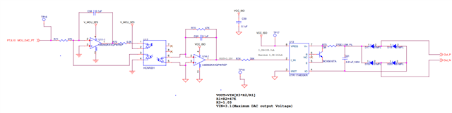
XTR117: Kindly provide a detailed review of the below schematic section
keep in mind that the output voltage of LM2902 can only rise to a voltage about 1.5V below the supply voltage. This may conflict with the circuit, especially for "U11-1". I would choose a rail-to-rail OPAmp for this task. Eventually the LMV321A or TLV9001 or similar.
And I don't understand "R73". Your circuit differs from figure 1 of datasheet of "XTR117", or figure 3. There should not be any resistor between "C61" and the "XTR117". This would heavily degrade the supply voltage decouping of "XTR117".
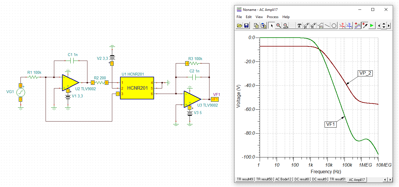
Also, some OPAmps may benefit from a decrease of "C58" and "C60" to something between 10...100pF. I would run a stability analysis to find suited values. If you want to low pass filter the DAC's signal, I would do it in front of "R71".
I agree with Kai’s recommendation of a rail-to-rail amplifier to avoid output limitations for U11 and U14. For the TIA, a low input bias current and low current noise amplifier is recommended. If you are considering a precision solution, the OPA392 (if it fits the current budget) or the lower power OPA391 are well-suited for this application.
Be sure to stay below 3.5mA on IRET - I assume the MCU is powered externally and is not contributing to your allowed current budget. And ensure that you are meeting the compliance voltage requirement of 7.5V between V+ and Io.
I am also unsure of R73’s purpose, please clarify further or remove if it is not necessary.
You can refer to this app note (pages 9-11) to determine the minimum value compensation capacitor for a given amplifier and feedback resistor to ensure TIA stability.
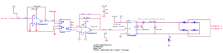
I had updated the schematic section as per your reviews. Please find the latest schematics and share me if you have any further reviews. And I have one doubt regarding the output voltage of U32 since it is powered by the isolated power supply from XTR(5V) . And while reverse calculations I got 3.25. Can you provide the relevant calculations using the circuit
I had updated the schematic section as per your reviews. Please find the latest schematics and share me if you have any further reviews. And I have one doubt regarding the output voltage of U32 since it is powered by the isolated power supply from XTR(5V) . And while reverse calculations I got 3.25. Can you provide the relevant calculations using the circuit
the OPA336 may not be a good choice here, because it is a micropower OPAmp and allows an output current of only 1...2mA. The "HCNR201" may need a higher current through its internal LED.
And there's still this unhelpful "R73". Please remove any resistor between the decoupling cap "C61" and the XTR117. The XTR117 will become instable with "R73" at this place.
Details on the protection circuit at the output of XTR117 can be found in figure 3 of datasheet and here:
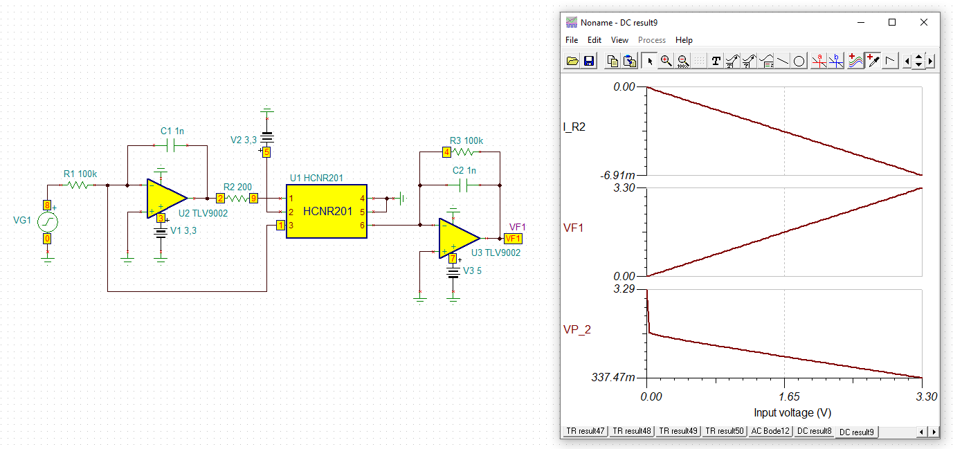
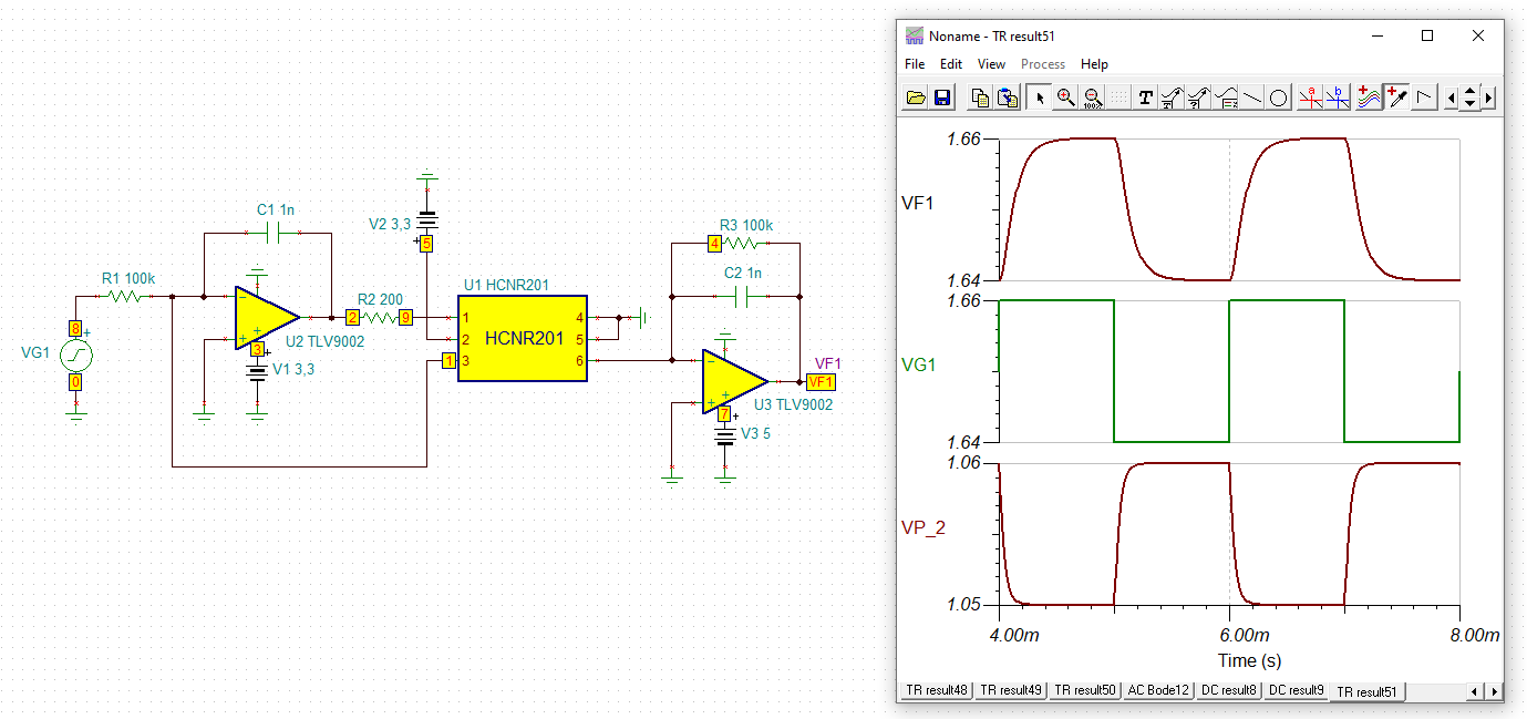
I looked into the HCNR201 a bit further. I am following your calculations. The maximum output voltage assuming K3 (max) of 1.05 and Vin (max) of 3.1 is 3.255V. I noticed K3 can vary up to a max of 1.07 over temp giving a max Vout of 3.317V.
With the 30k resistor and Vout of 3.255V, you can expect a max I_in of 108.5uA as you have annotated. So, for Vin range of 0 to 3.255V, your I_in will vary 0 to 108.5uA. You may expect IO to vary 0 to 10.8mA. But, note that you will never see 0mA at IO. The quiescent current of the XTR117 + current drawn from VREG sets the lower limit of IO. Does this answer your question?
OPA336 ISC is +/-5mA. All datasheet specs including the value of K3 are for an LED forward current of 10mA. The OPA391 or OPA396 is a good option. It is RRIO, low power (24uA) and has an ISC of 60mA.
I agree with Kai, you should not need R73. You have reverse voltage protection with the diode bridge. I see you added a Zener diode which will provide overvoltage protection. You may consider placing this between the V+ and Io terminals as in Figure 3 of the XTR117 datasheet.