Other Parts Discussed in Thread: OPA547
- Problem Description:
Our product oscillates when the output current is -10mA. Step by step positioning shows that it is the OPA548 device that oscillates
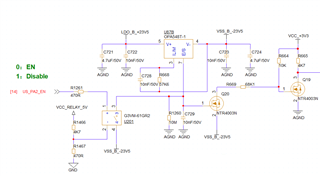
- Application circuit:
e.g. (Figure 1), G=1, external pure resistance load,DC output
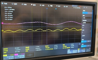
- Oscillation waveform:
230mV at 1.6MHz, as shown in Figure 2. Figure 3 shows another OPA548 with the same test condition and amplitude of 30mV
- Production conditions:
Current range from -5 mA to -16mA. Current outside this range will not oscillate, independent of the output voltage
Current measures:
1. We change R633 from 100R to 0R, and the amplitude and frequency of oscillation remain unchanged.
2. We replaced the OPA548, and the amplitude was reduced to 100mV, but the oscillation was not completely eliminated
3. The waveform of the negative power supply was measured without 1.6MHz ripple
4. This phenomenon exists for different batches of OPA548
Please help to analyze the reasons and improvement measures. Thank you very much!
Figure 1: OPA548 application circuit: Power supply ±23V, NC indicates the device is not welded.

Figure 2: CH1 (yellow) indicates the OPA548 pin 6-out output waveform, and CH2 (purple) indicates the pin 1-input waveform
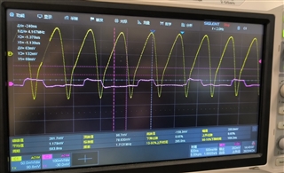
Figure 3: Another OPA548 on the same board with the same test conditions as in Figure 2