This thread has been locked.

If you have a related question, please click the "Ask a related question" button in the top right corner. The newly created question will be automatically linked to this question.

OPA192: The related output resistance of this OPA192 device?

Part Number: OPA192

I hope to know which resistance value listed in P. 6, P. 9, P11 is the output resistance of this OPA192 device? Or none of these 3 resistance values is the output resistance value of this device and the output resistance of this is determined by some other ways instead of the 3 values listed in these several pages?

Thanks

yenwu lo

  • Hello Yenwu, 

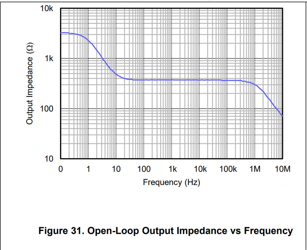
    The output impedance is shown in Figure 31 across frequency and is 375 ohms in the mid band frequencies. This aligns with 375 ohms on pages 9 and 11. The other two specifications are the short circuit current of the device and are DC measurements. Let me know if you have any further questions. 

    Best Regards, 

    Chris Featherstone

  • Thanks. Chris Featherstone,, On page 11, the circled output short circuit current shows +/-65mA, my question is: If output resistance is 375 ohm, then if Vs= 5V, the output short circuit current should be around 5V/375ohm= 13.3mA instead of 65mA? 

    Also this page 11 output short circuit current shows both +/- sign, not sure how this + 65mA come from where? because according to TI convention, this +65mA means a current which is flowing into the output node of this device? 

    Not sure if you can help to explain more on these above questions?

    Thanks

    yenwu lo

  • Hello Yenwu, 

    There are a few things to consider. The open loop output impedance plot is measured across frequency or at AC. The DC output current is a separate measurement performed at 0 Hz or DC. If we look at the open loop output impedance plot it is a curve that represents Zo that is made up of real and complex components. The real component we consider the DC component, Ro. This DC value in the graph is approximately 3.1 kohm.

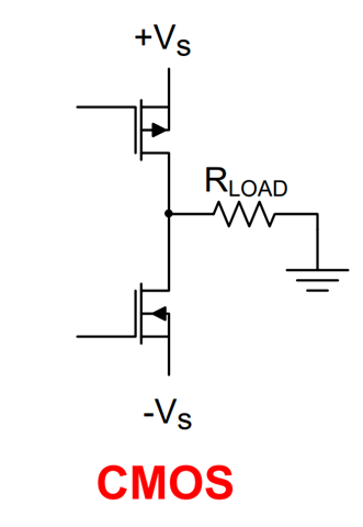
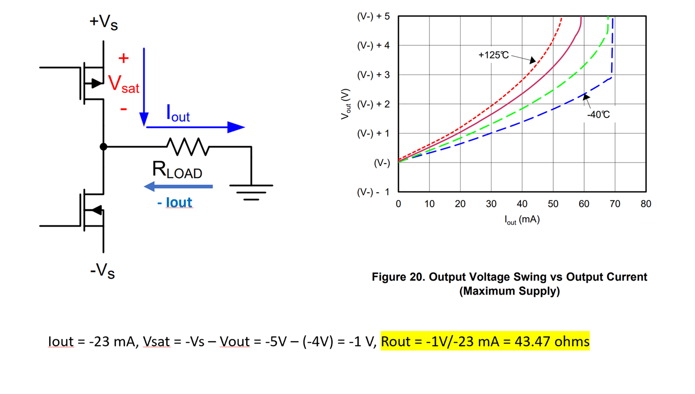
    The closed loop output impedance Rout = Ro // R_load where Ro is the DC open loop output impedance. If we wish to calculate the closed loop DC output impedance Rout across output current we can use the Vout vs Iout plots. Usually the datasheets have two plots one for sourcing current from the amplifier to the load and one sinking current into the amplifier from the load. Unfortunately the OPA192 datasheet is missing the sourcing plot and we are working to get this added into the datasheet.

    As and example of how to relate the closed loop DC output impedance Rout to the DC output current I will use the available sinking current plot. Please note that the values for Iout (sinking current) are made positive on the x-axis for easier comparison to the sourcing plot when it is available. The green dashed line represents room temperature. The steep fall off at 65 mA is the short circuit current. When Vout reaches 0V the output current is 65 mA. Below I chose the point where the output voltage is at -4V and the output current is |-23 mA|. At this point Rout = 43.47 ohms.

    For more insight into this topic we have a detailed series regarding the DC components of the output stages under the section called "Input and Output limitations". 

    https://www.ti.com/video/series/ti-precision-labs-op-amps.html

    I hope this information helps to clarify the specifications. 

    Best Regards, 

    Chris Featherstone

  • Thanks. Chris, I hope to ask a few more questions as shown below, 

    1. The 47.43 ohm you calculated in your example can also be used as the output resistance when output is sourcing current or not? when 

    2. the DC open loop output resistance is about 3.1K ohm as you mentioned, can we use this 3.1kohm resistance value to get the DC close loop output resistance or not? Can  we relate this 3.1k ohm to the close loop DC output resistance 47.43ohm? 

    3. when we talk about output resistance for an OpAmp component, we usually refer to the closed loop output resistance? because OpAmp usually is running at closed loop application? 

    4. What is the use of this 375 ohm open loop output impedance in general? 

    Thanks

    yenwu lo

  • Hello Yenwu, 

    The resistance Ro tells us the inherent output impedance of the output stage transistors of the amplifier. When you close the loop and add a load resistor the Rout impedance is the parallel combination of Ro and RLoad. In an ideal world Ro would be 0 ohms meaning that the amplifier can deliver infinite output current to the load and the desired output voltage would be unaffected. In reality the amplifier can only deliver so much current and this is where the Vout vs Iout plots provide us the information on how much current the amplifier can deliver to the load. You can use the same method of calculating Rout as I did above with either the sourcing or sinking current plots. 

    The 375 ohms is the output impedance at frequency. We use the output impedance information at frequency most commonly for stability analysis. If you are interested in how the output impedance is used in stability analysis we have a series on this topic as well that can be found here:

    https://www.ti.com/video/series/ti-precision-labs-op-amps.html

    Best Regards, 

    Chris Featherstone

  • Thanks. Chris, this resolved my issues,