This thread has been locked.

If you have a related question, please click the "Ask a related question" button in the top right corner. The newly created question will be automatically linked to this question.

OPA192: Capative load drive via dual feedback

Part Number: OPA192
Other Parts Discussed in Thread: OPA627

Hi team,

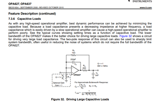
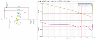
While going through oure precision video Stability- isolator resistor, the dual feedback is introduced as following:

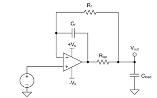
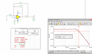
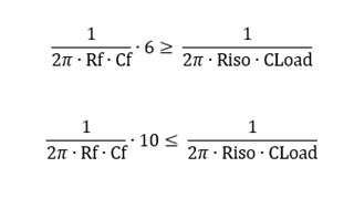
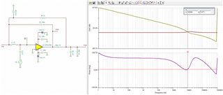
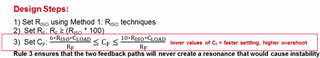
And the design steps are ad below, could you pls help to expalin a little more that how the Cf value formula comes from?

Thanks

Best regards

Mia Ma

  • I think the original appeared in the OPA627 datasheet, circa 1985

  • I found another file where I had done some work on this, but not a derivation. These equations work very well where Ro and Rx are the same thing. I call this an imbedded integrator circuit. 

    Imbedded integrator with OPA725.TSC

  • Hi Mia,

    The formula is in the form of an inequality based on the pole caused by the interaction of Rf and Cf, and the pole caused by the interaction of Riso and CLoad.

    Using algebra we can rewrite the inequality in the form that expresses the pole frequencies...

    This form expresses that the poles should be separated in frequency by at least a factor of 6, but no more than 1 full decade apart. The purpose of this is to avoid complex conjugate poles in the feedback loop, which looks like gain peaking in the 1/Beta curve and can result in reduced phase margin and instability.

    In the following simulation the pole locations are both set to ~1.5MHz, resulting in complex conjugate poles. There is clearly gain peaking in the 1/Beta curve and the phase margin is only 7°.

    Following the precision labs minimum recommendation for Cf (factor of 6), the poles are sufficiently far apart to remove the complex conjugate and the system is stable.

    The minimum frequency separation by a factor of 6 is somewhat conservative and is meant to remove complex conjugates while accounting for process variation, component tolerance, etc. The example that Michael showed from the OPA627 recommends a minimum frequency separation by a factor of 2 which could be sufficient depending on the application.

    Thanks,

    Zach