Hi, Could you please review below circuit and let me know if any issues. .
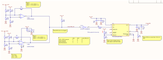
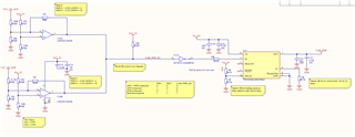
in this circuit, two Voltage rails both are 12V, whenever one of them is present, camera power should be ON. I'm using LM393LV in inverting input, having threshold voltage of VA1 = 3.55V and input is greater than 12.0V, the ouput of comparators will be low. When input is less than 11.5V and VA2 = 3.39V, output will be high. Than, I connect both outptus to create wired OR gate and get final camera power enable signal. then I have connect a not gate, SN74LVC1G04DBVR and power switch has active high input pin. and use power switchTPS1H200AQDGNRQ1 to control camera power.
Could you check resitor values for LM393LV and complete circuit? any feedback is welcome. Further details are added in circuit diagram.
Thanks in advance.