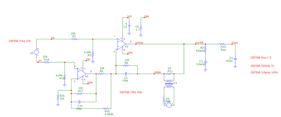
Hi, I have a circuit that I am using for driving a anti-aliasing RC filter for the input to an ADC. Our signal conditioning uses the TLC082AI in a differential amplifier configuration as sown in SLOA039A Figure 16. This circuit has worked well for us as it provides gain, offset, a differential measurement, and good common mode rejection. My question is related to increasing the capacitor in the anti-aliasing filter to give us the full precision on the ADC as well as increasing the bandwidth. I'm looking at going from a RC of 50 ohm and 47nF to 1.5 ohm and 400nF. Another improvement is to move to an amp with higher GBW and less offset voltage such as OPA365.
So my concern is checking the stability of the circuit with the larger load cap. I'd like to measure phase margin but am a little puzzled at how to properly break the loop and measure open loop gain. I've broken one loop with the transformer and resistor (K1 and R11), but there are two other loops. Loopgain is then Vresp/Vfdbk. Can you suggest a good method for verifying stability or perhaps another way entirely? The only other thing I've been able to come up with is checking the circuit overshoot during a full scale step or perhaps keeping the peaking of the closed loop transfer function below 3dB but these seem like more crude checks which may not be full-proof.
Thanks,
Chris


